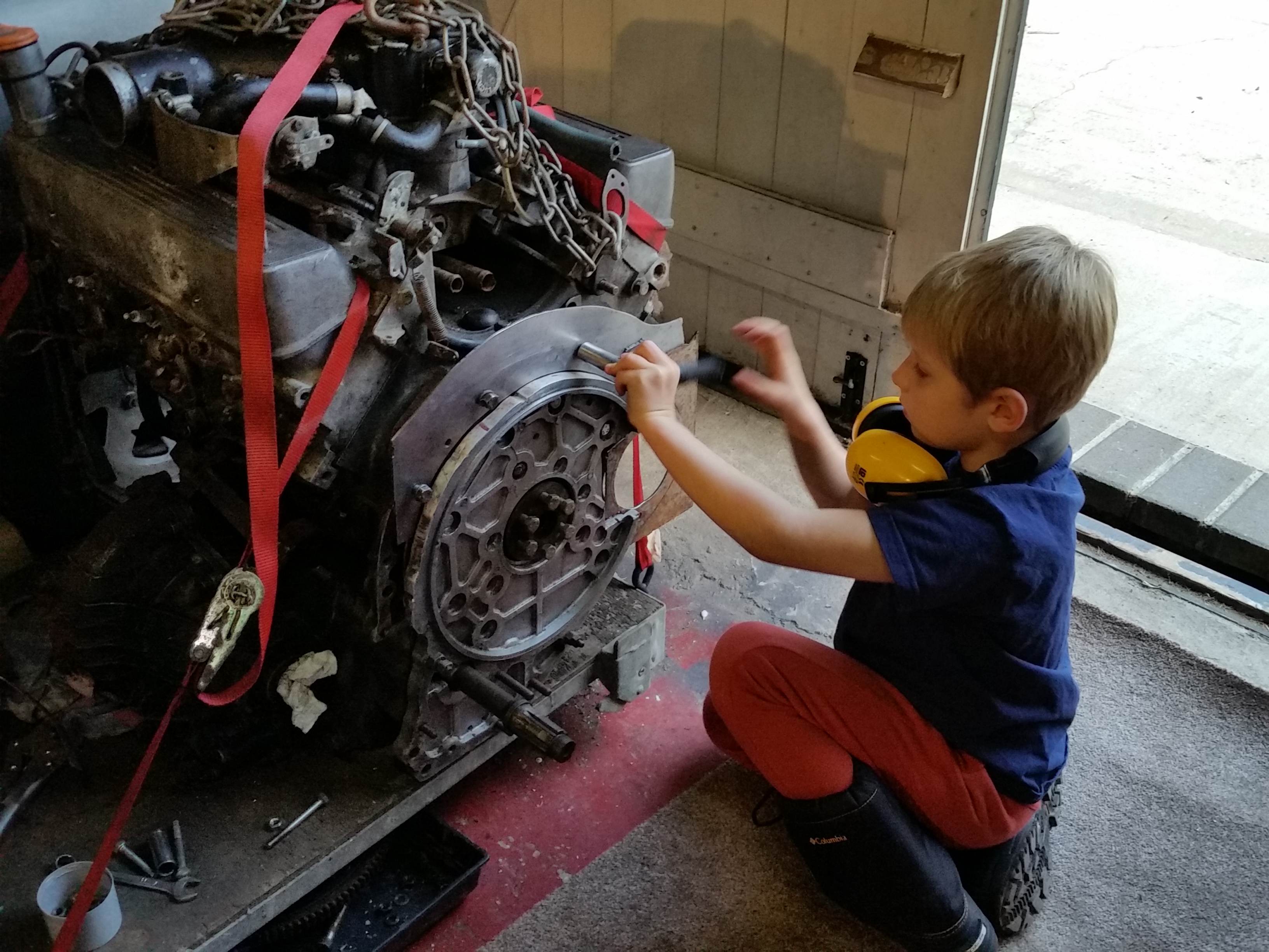
November 2016. Starter motor adapter plate.
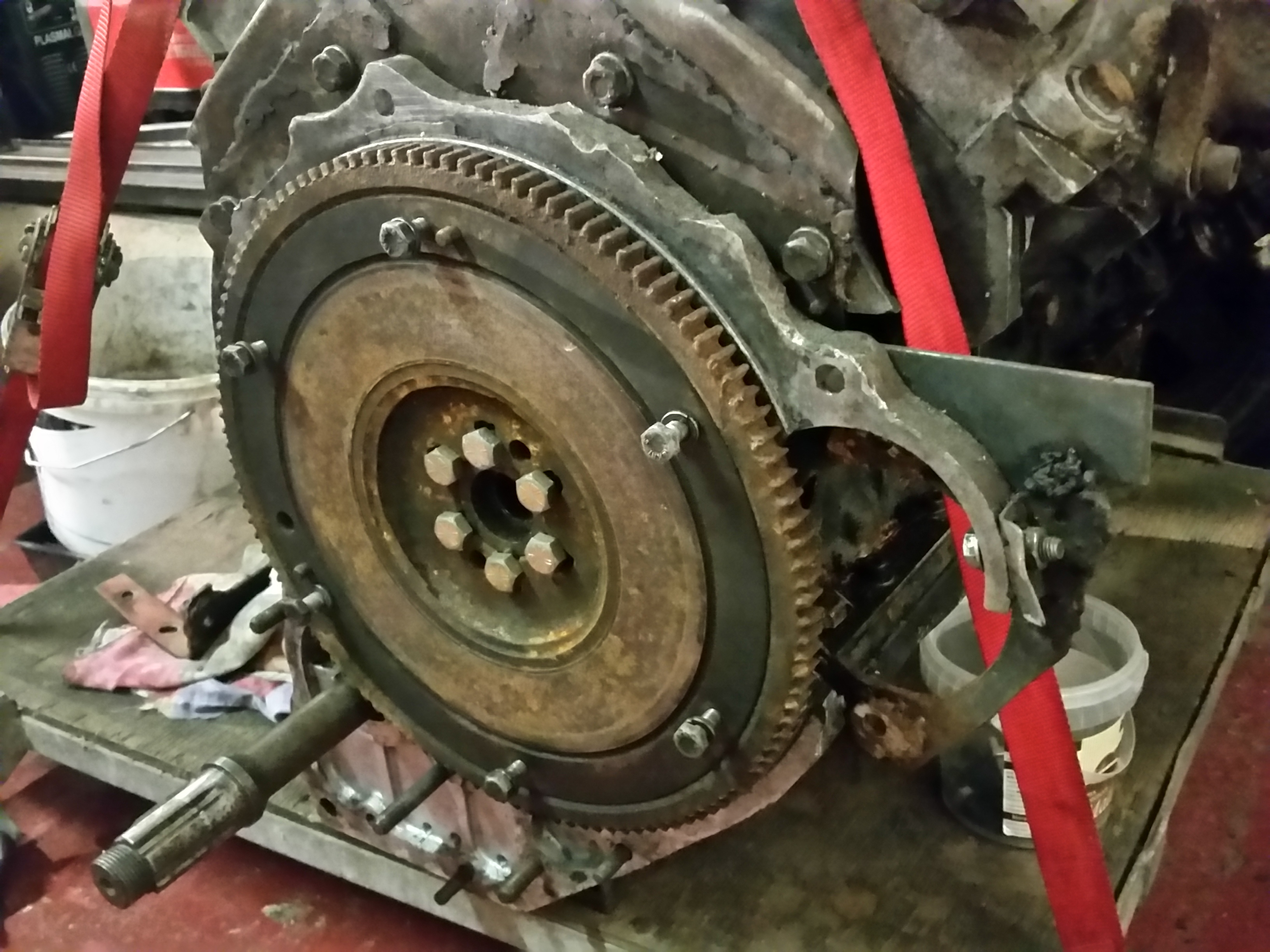
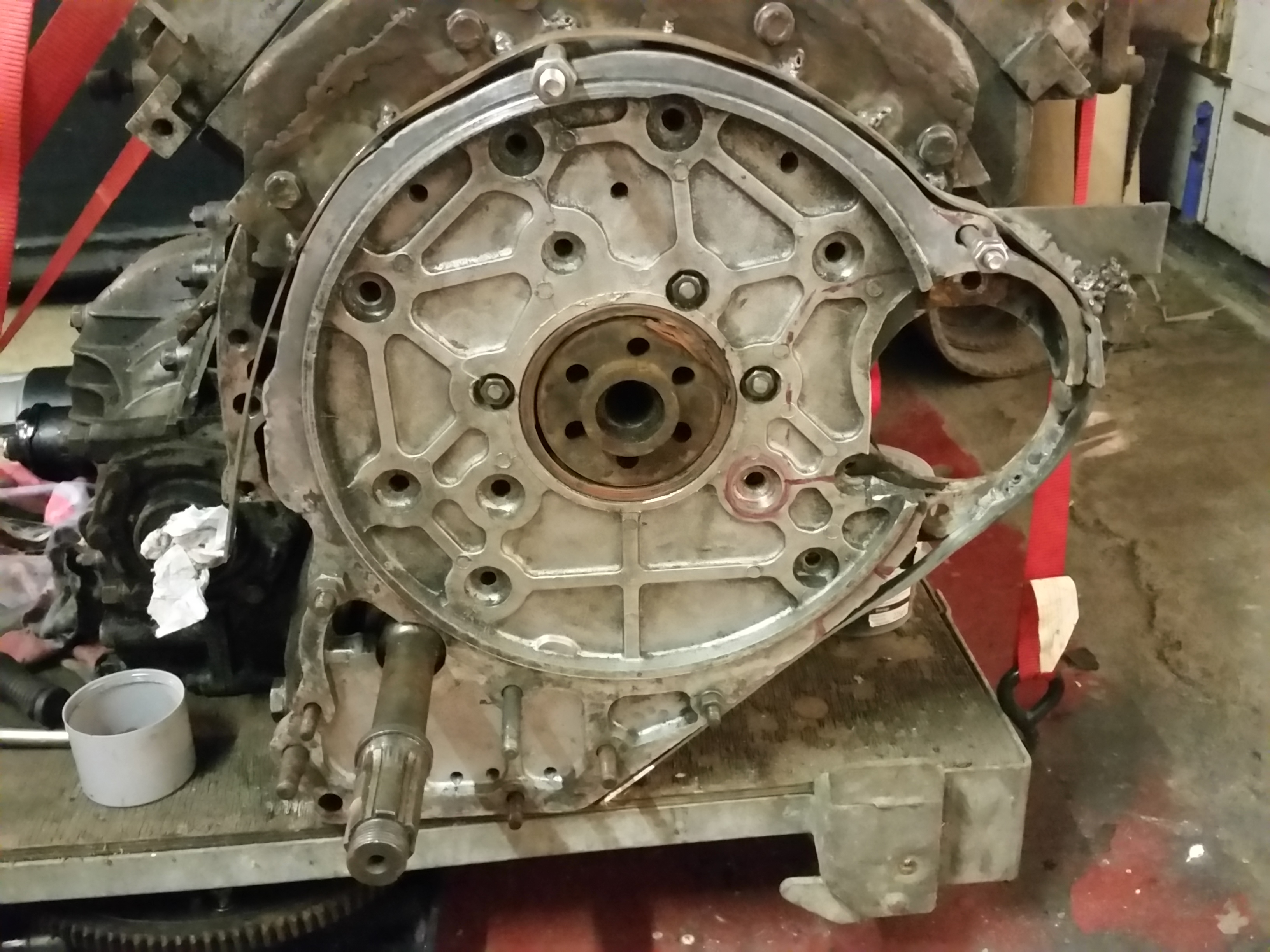
Adam had needed to replace the ring gear on the flywheel as the old one had become somewhat chewed after a few years of use.
The idea is to remove the adapter and reinforce it to prevent flex, which I think was allowing the starter teeth to lose engagement with the ring gear, thus causing the damaged teeth.
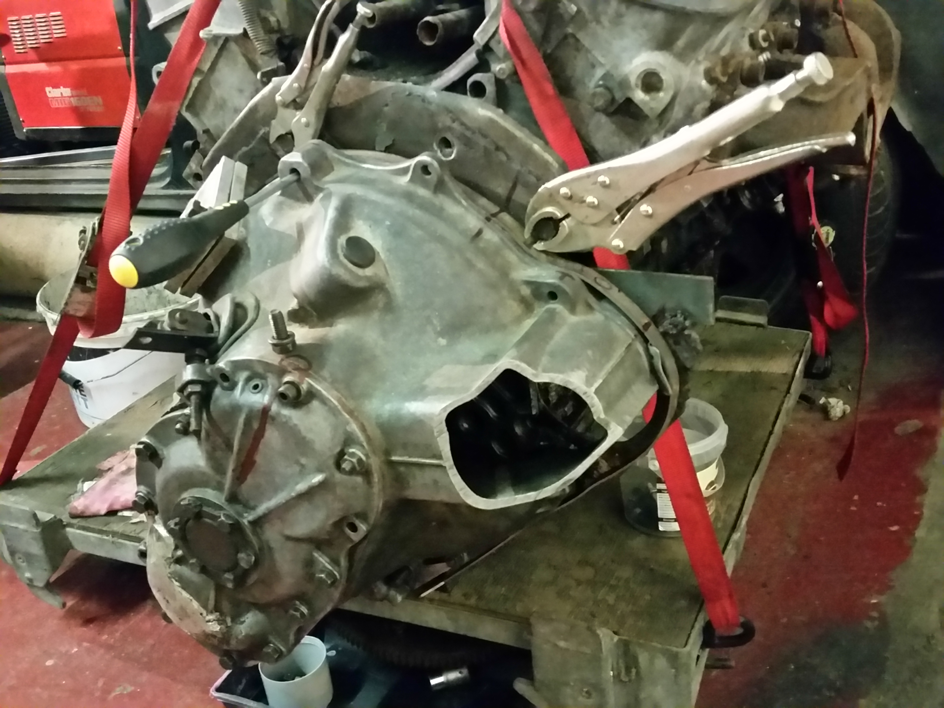
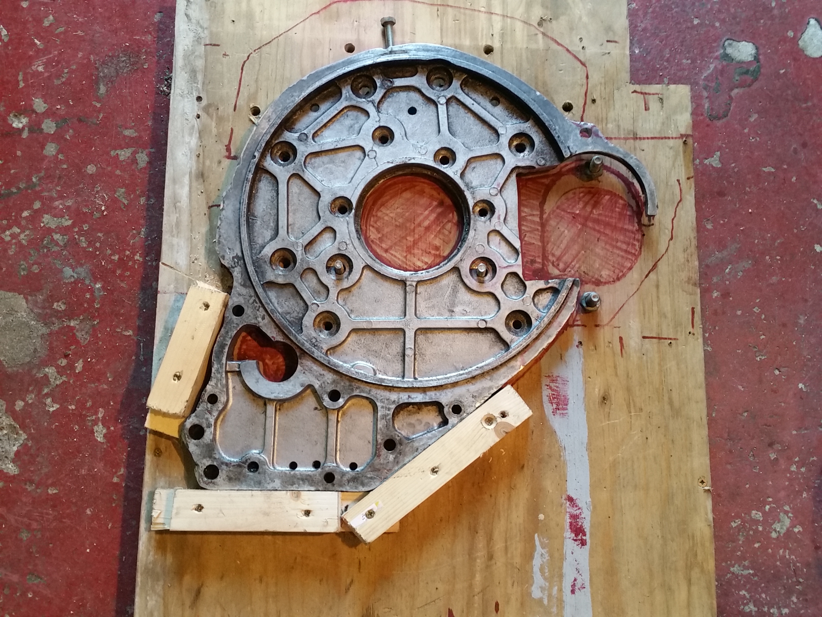
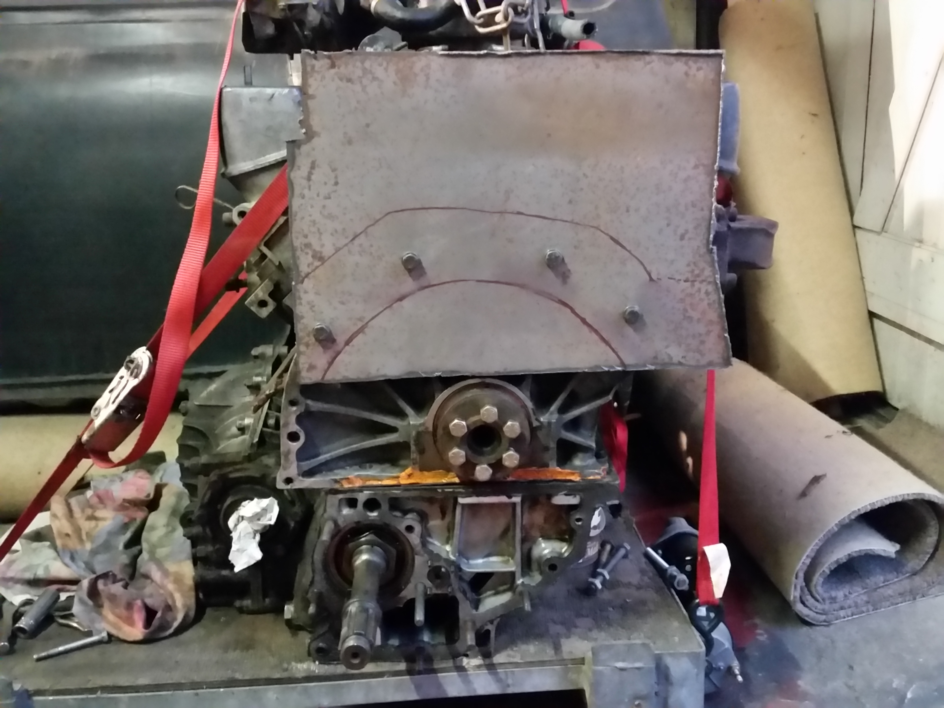
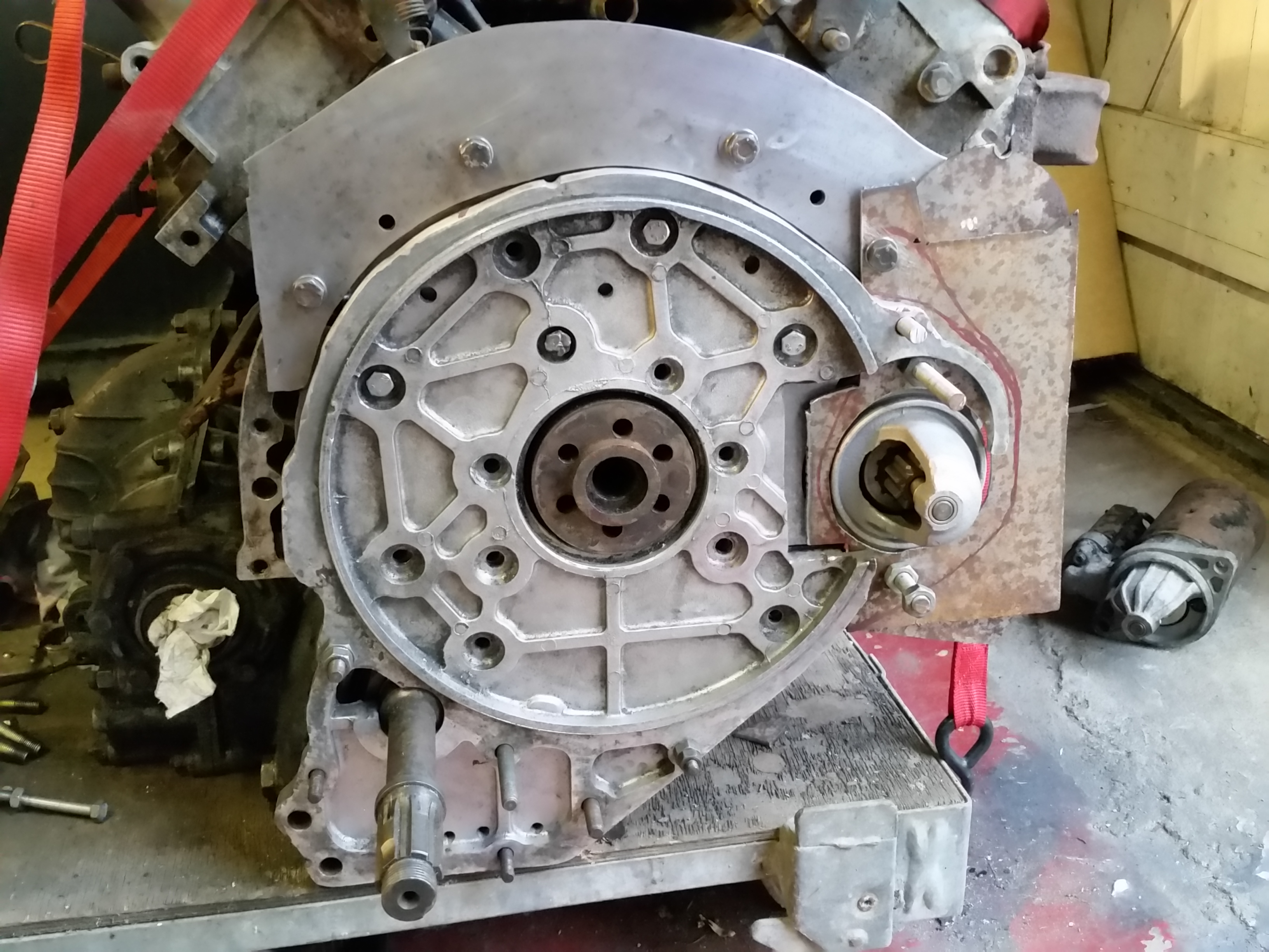
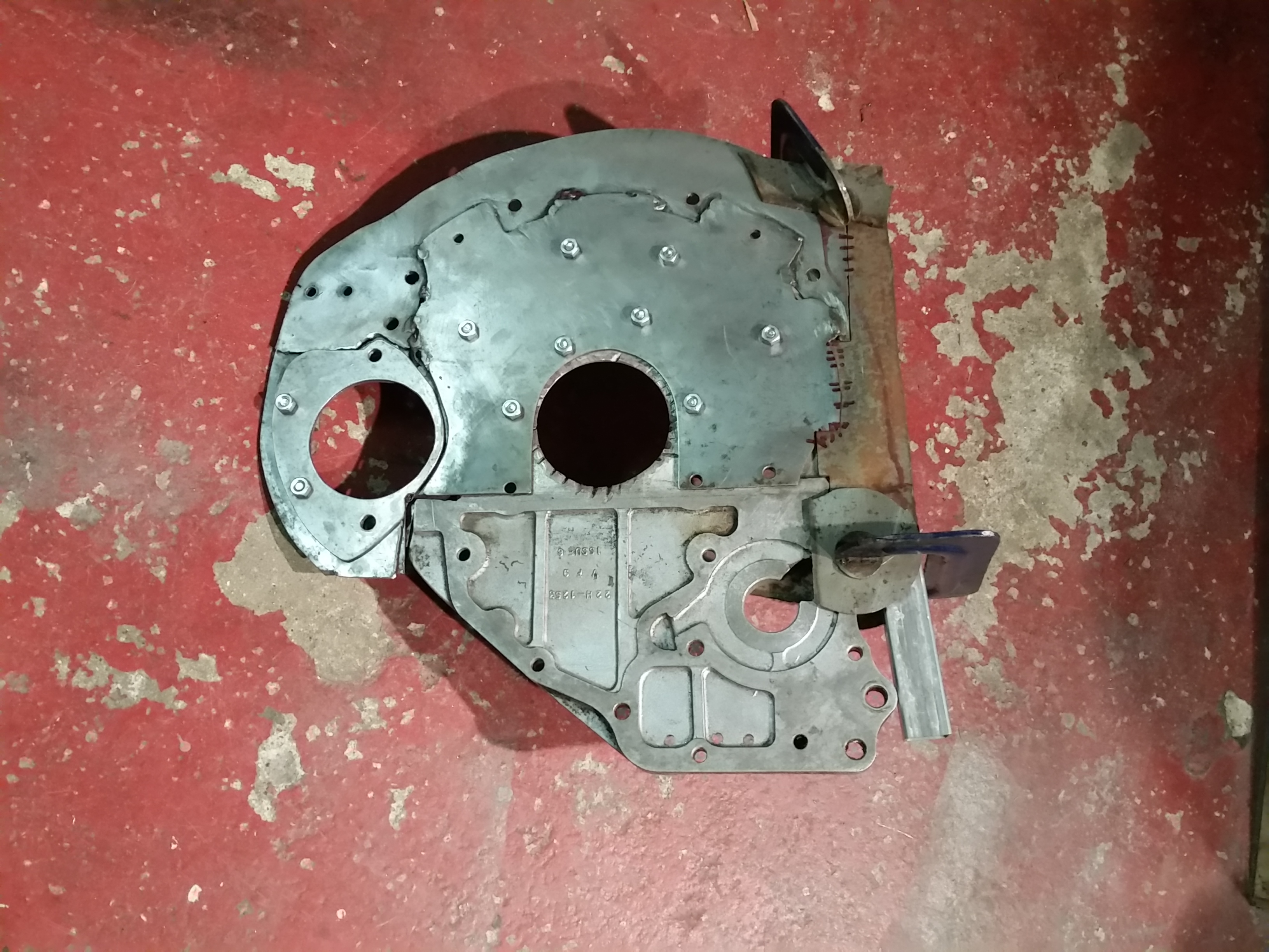
Stripping bits off to reveal the glory of some vintage orange goop :)
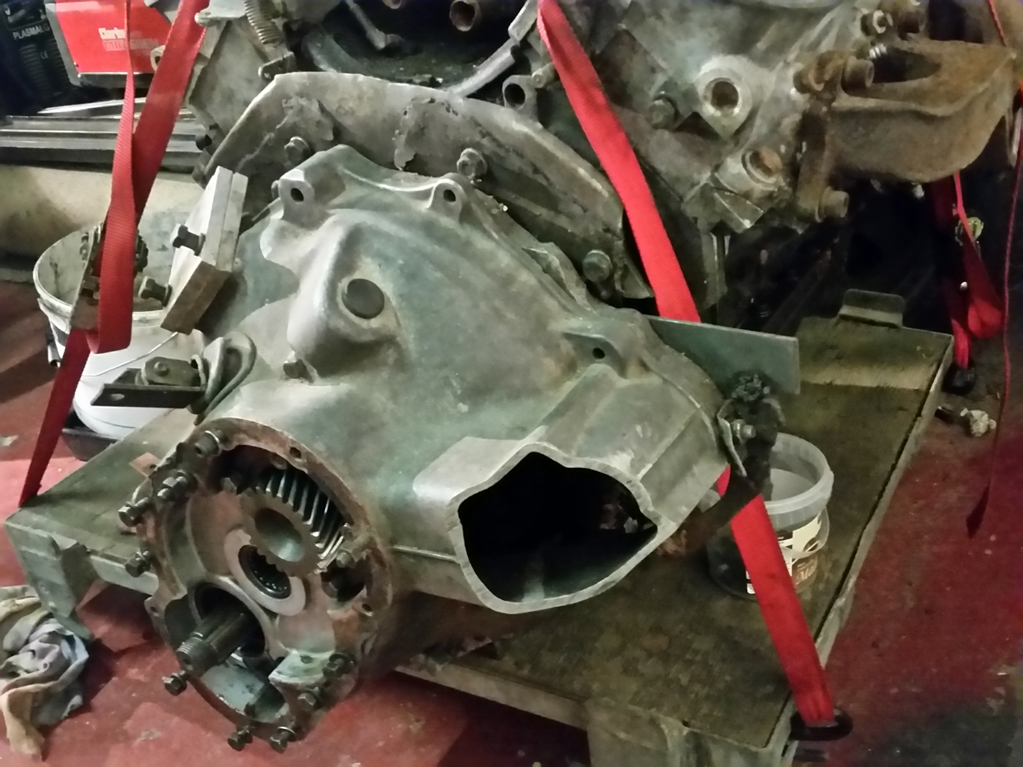
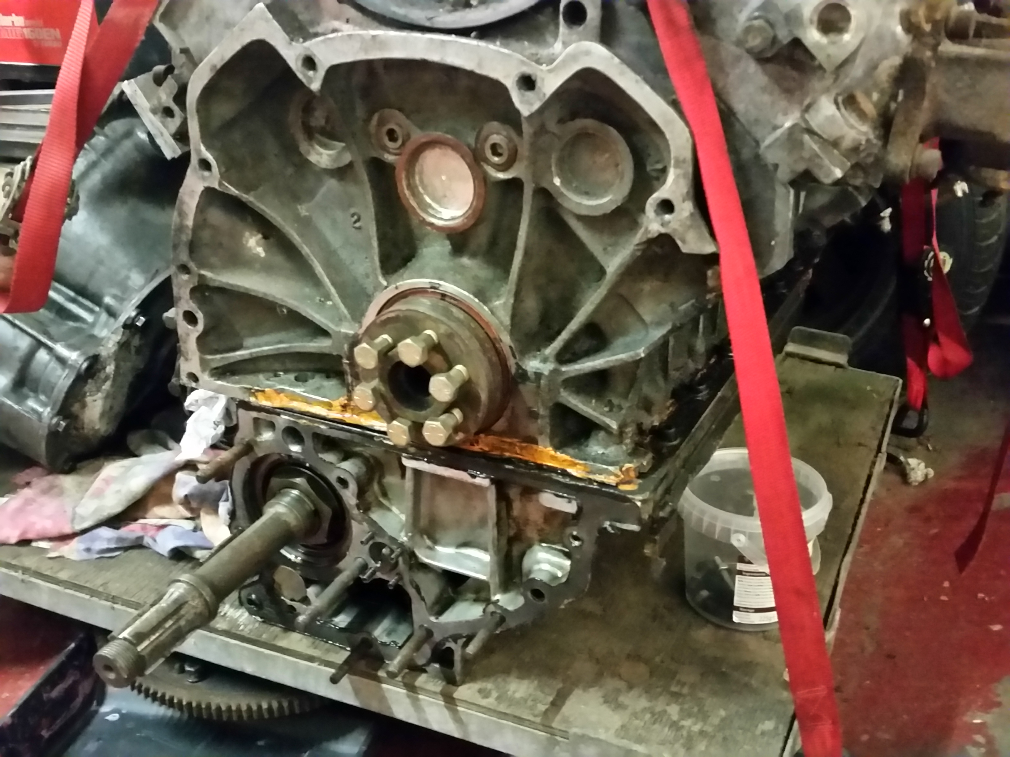
The old adapter plate is ugly but was fairly functional, so should still do the job with the addition of a steel band to prevent flex.
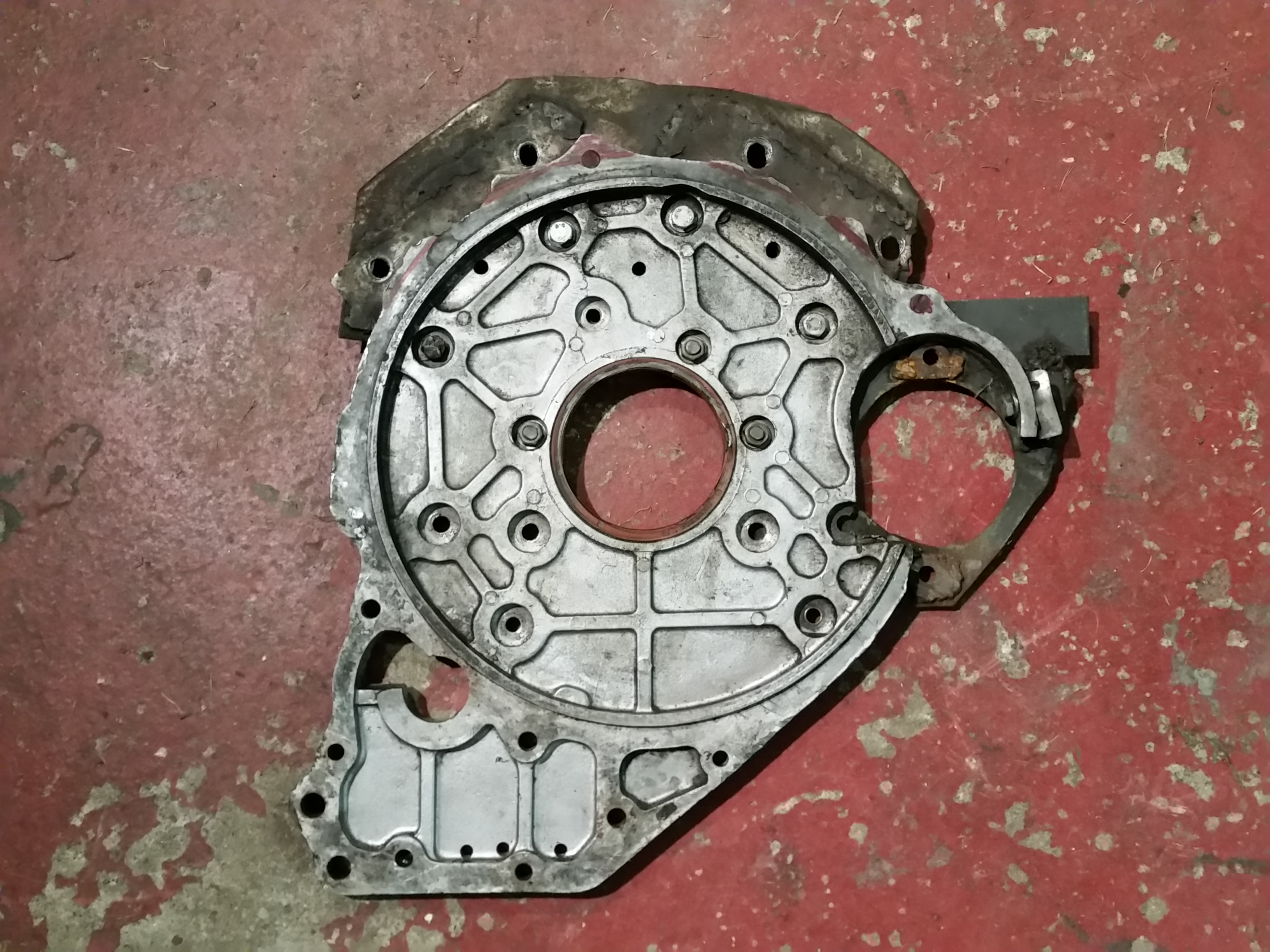
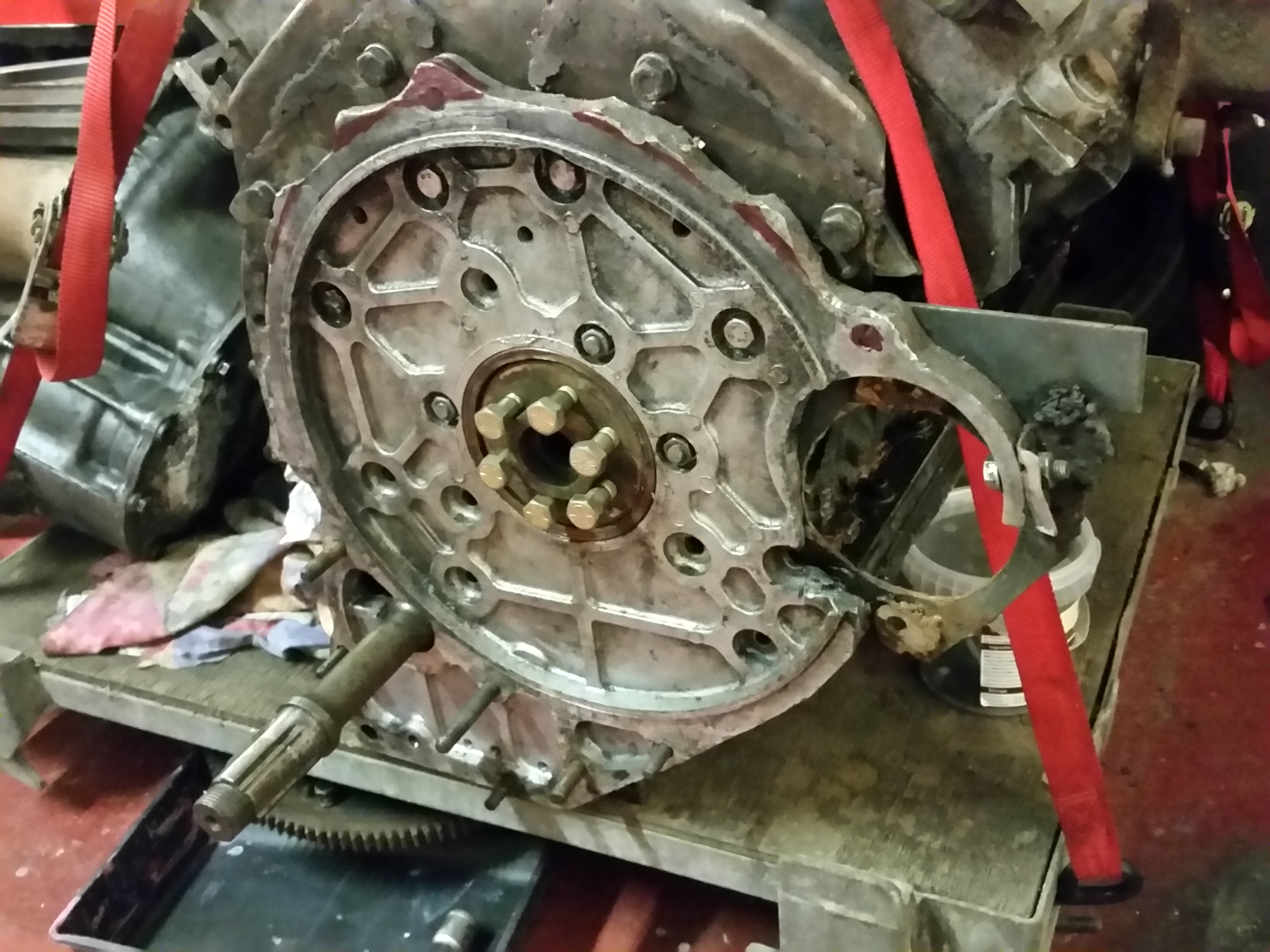
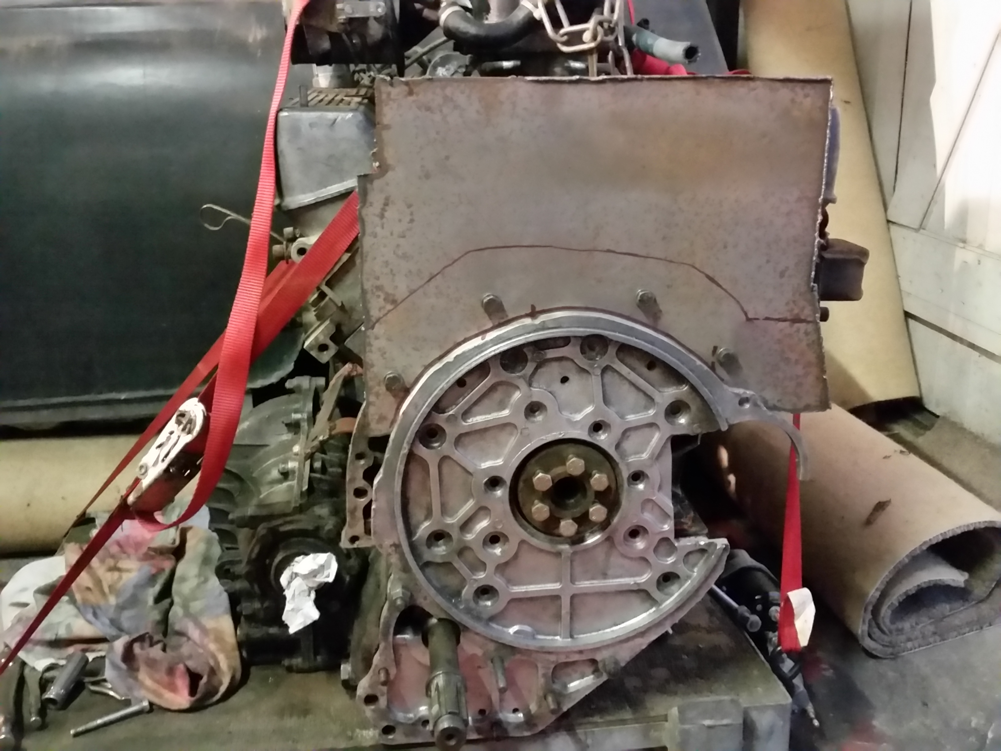
Off with the lugs from the backplate to give a nicer curve to work with, and
room for welding.
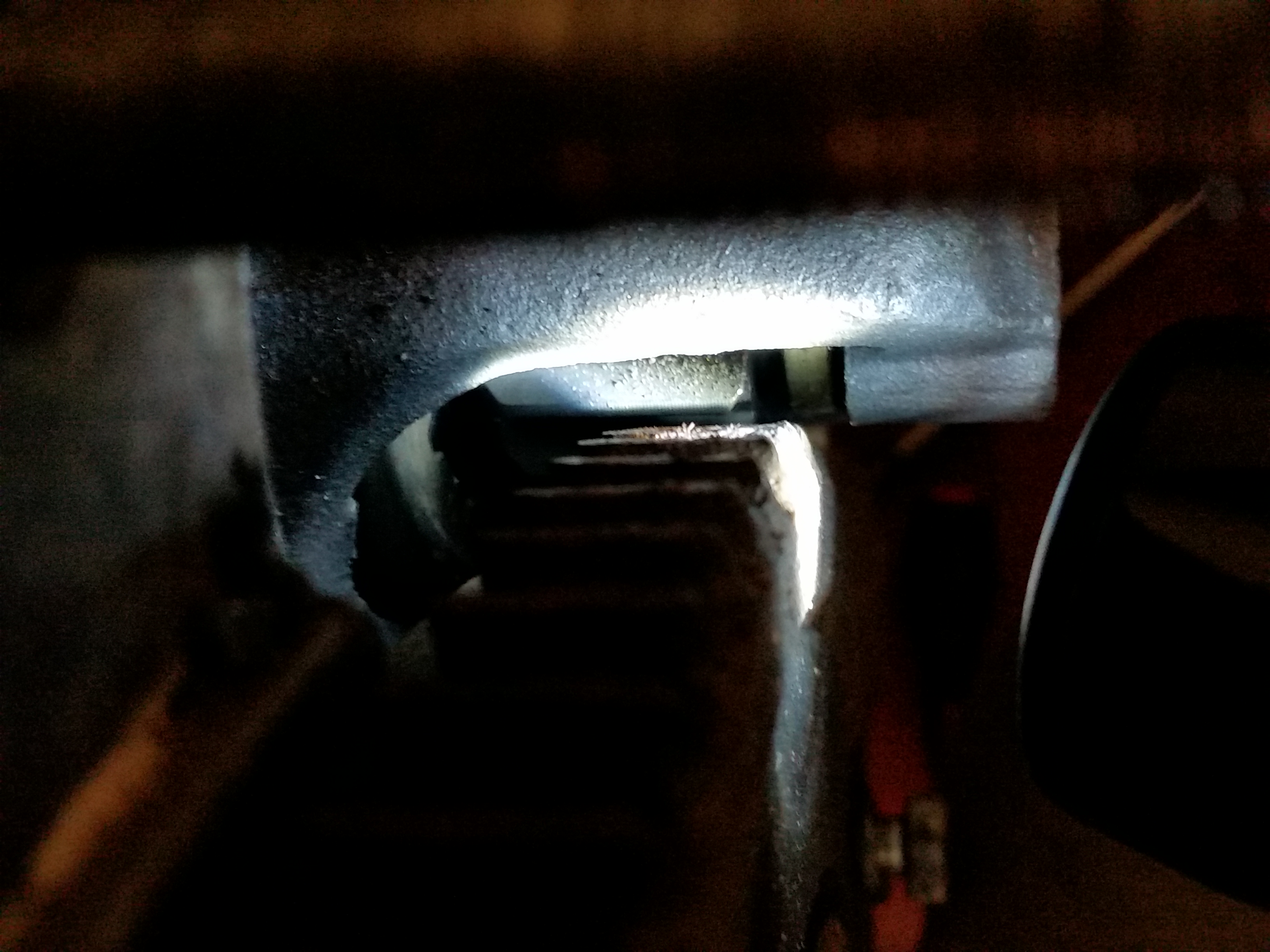
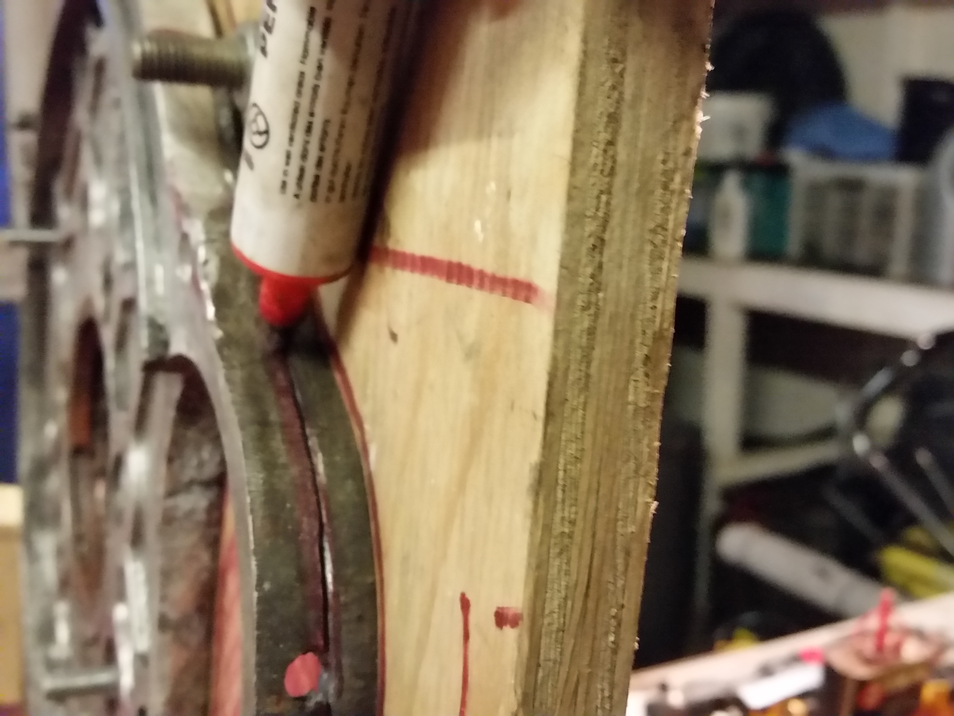
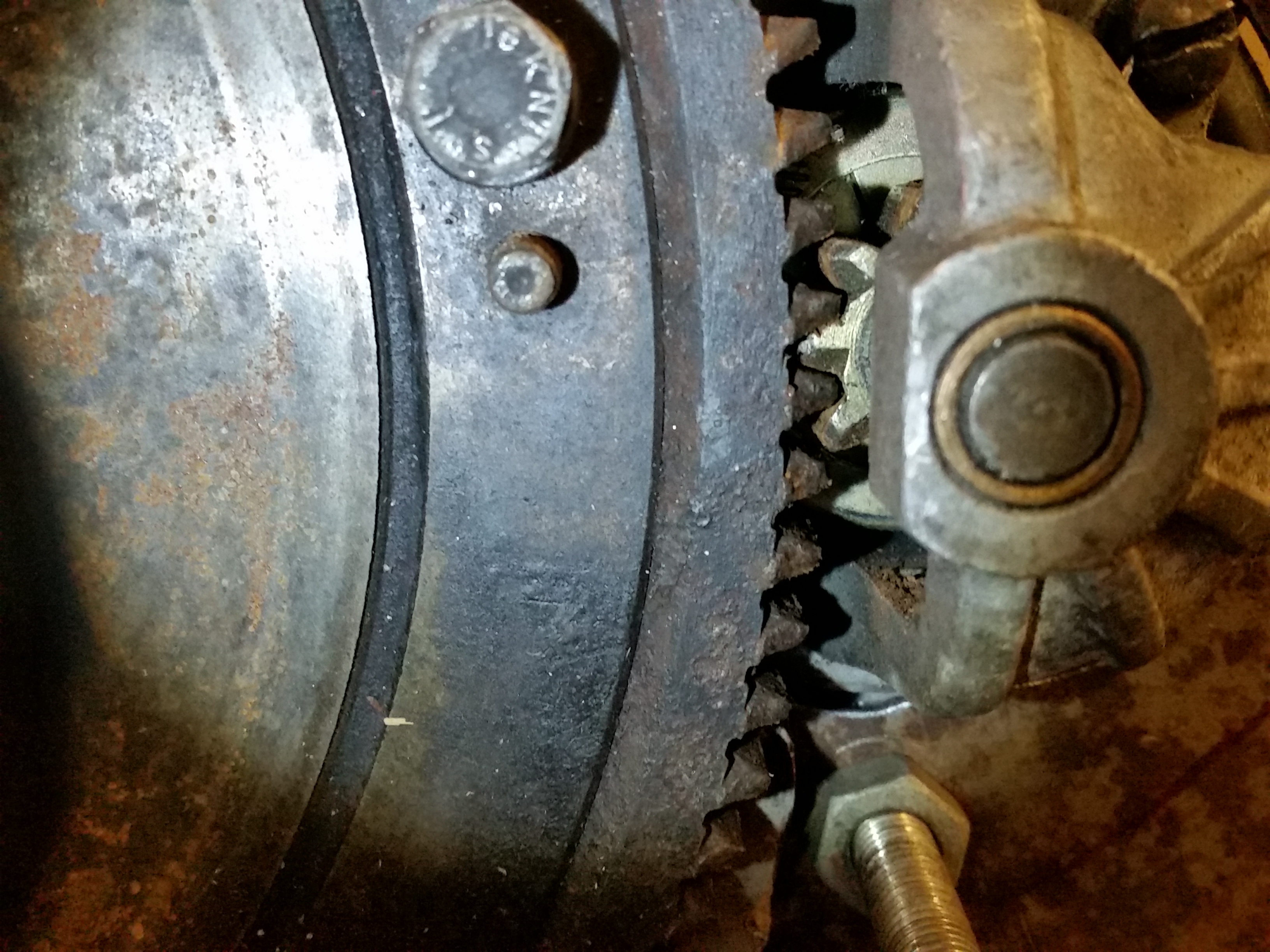
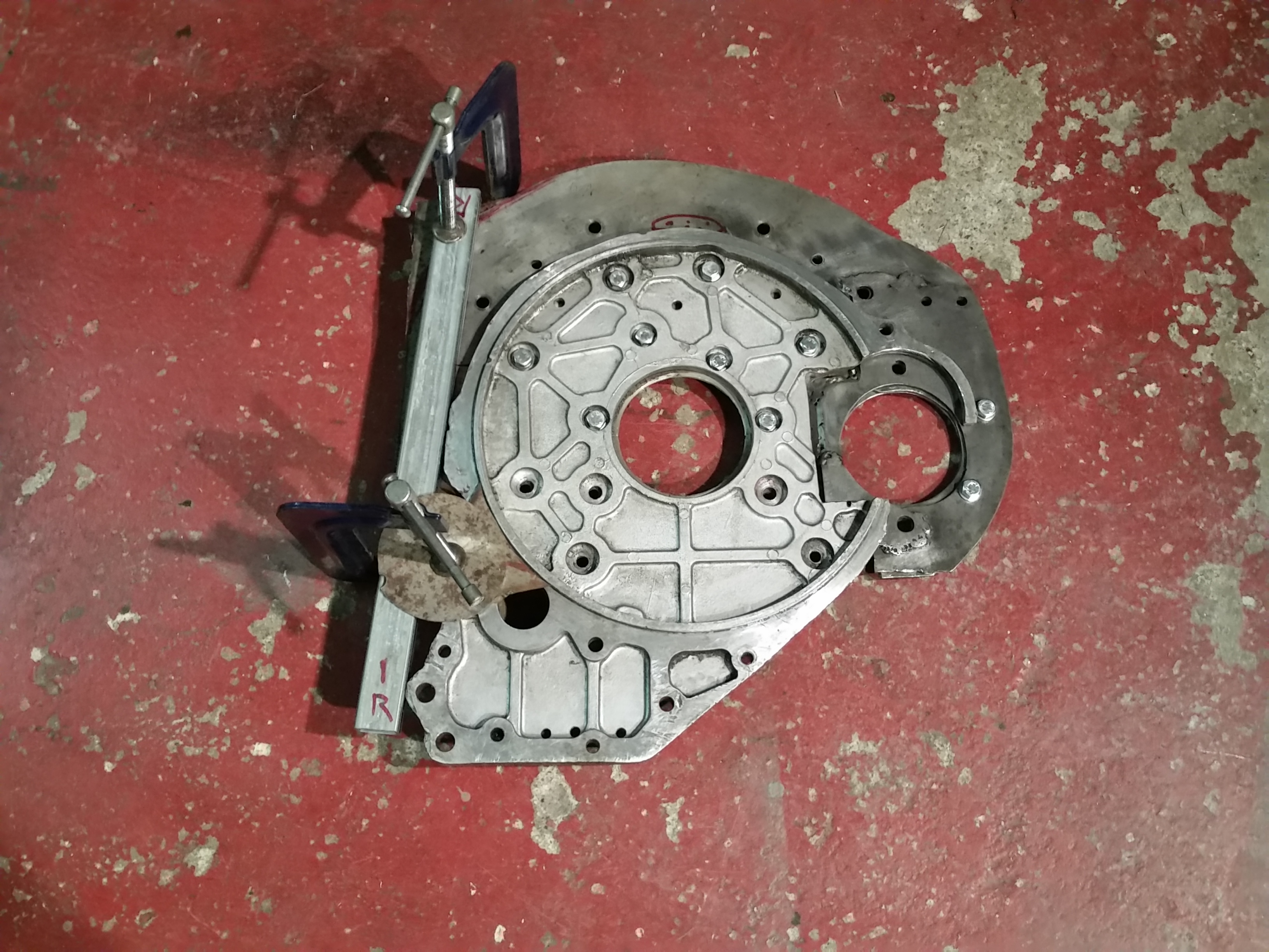
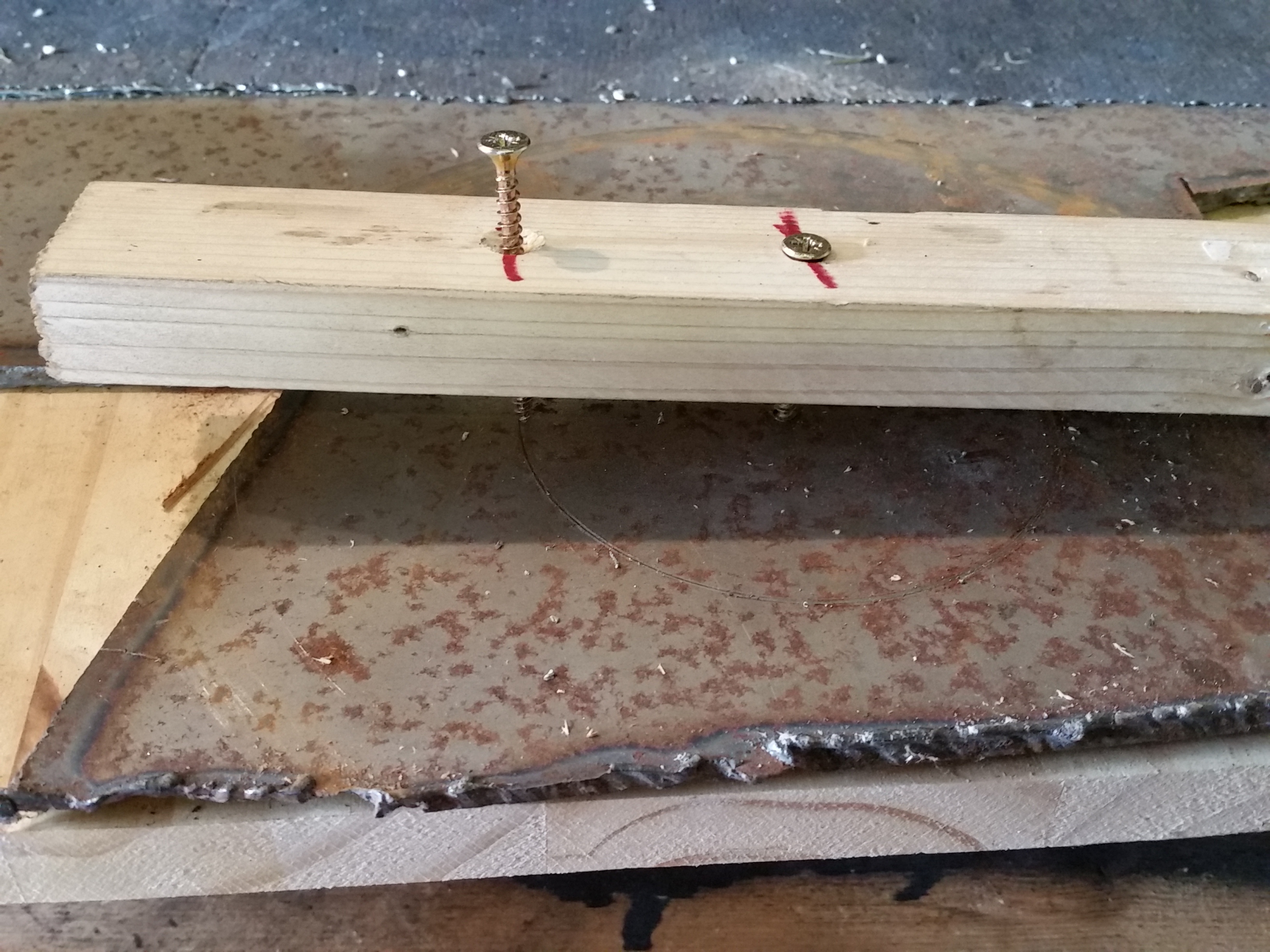
With the steel band tacked in place, the starter loop if definitely stiffer.
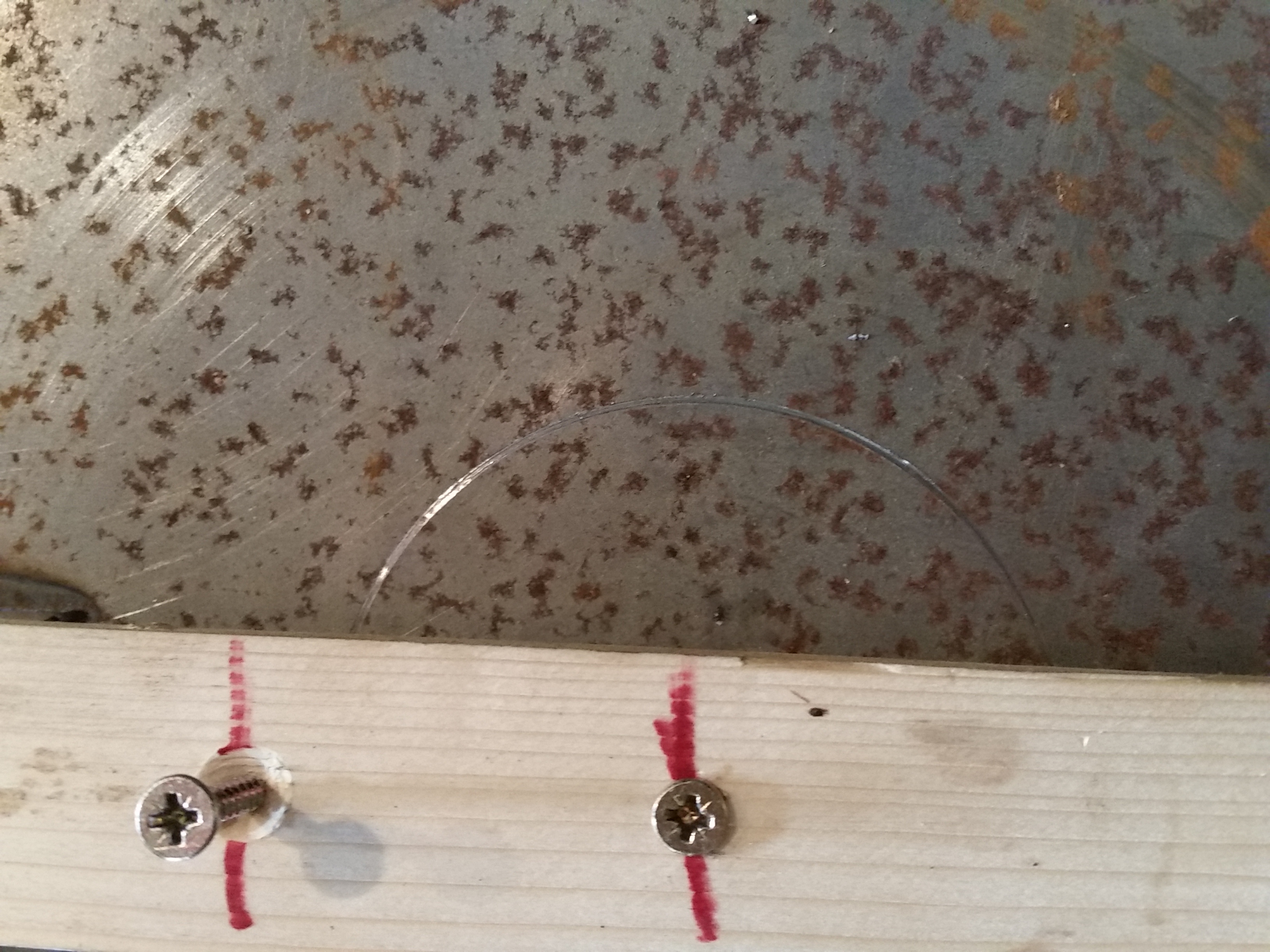
A quick check shows the starter teeth meshing nicely with the ring gear, apart
from a bit of unwanted offset, which means there is not full engagement, and
that's going to be good for teeth!
Ok, we could go with the adapter as is and it would probably be ok for another
few years more use, or could make a new adapter based on what was learnt from
the 'prototype'. Now that would be a thing!
Plan B
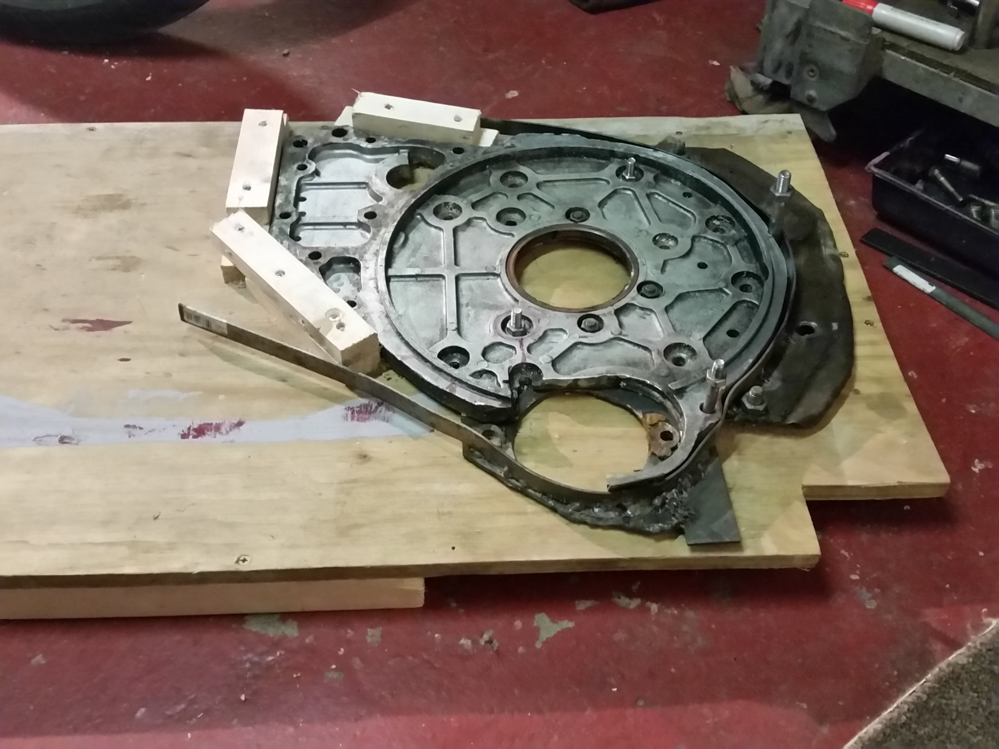
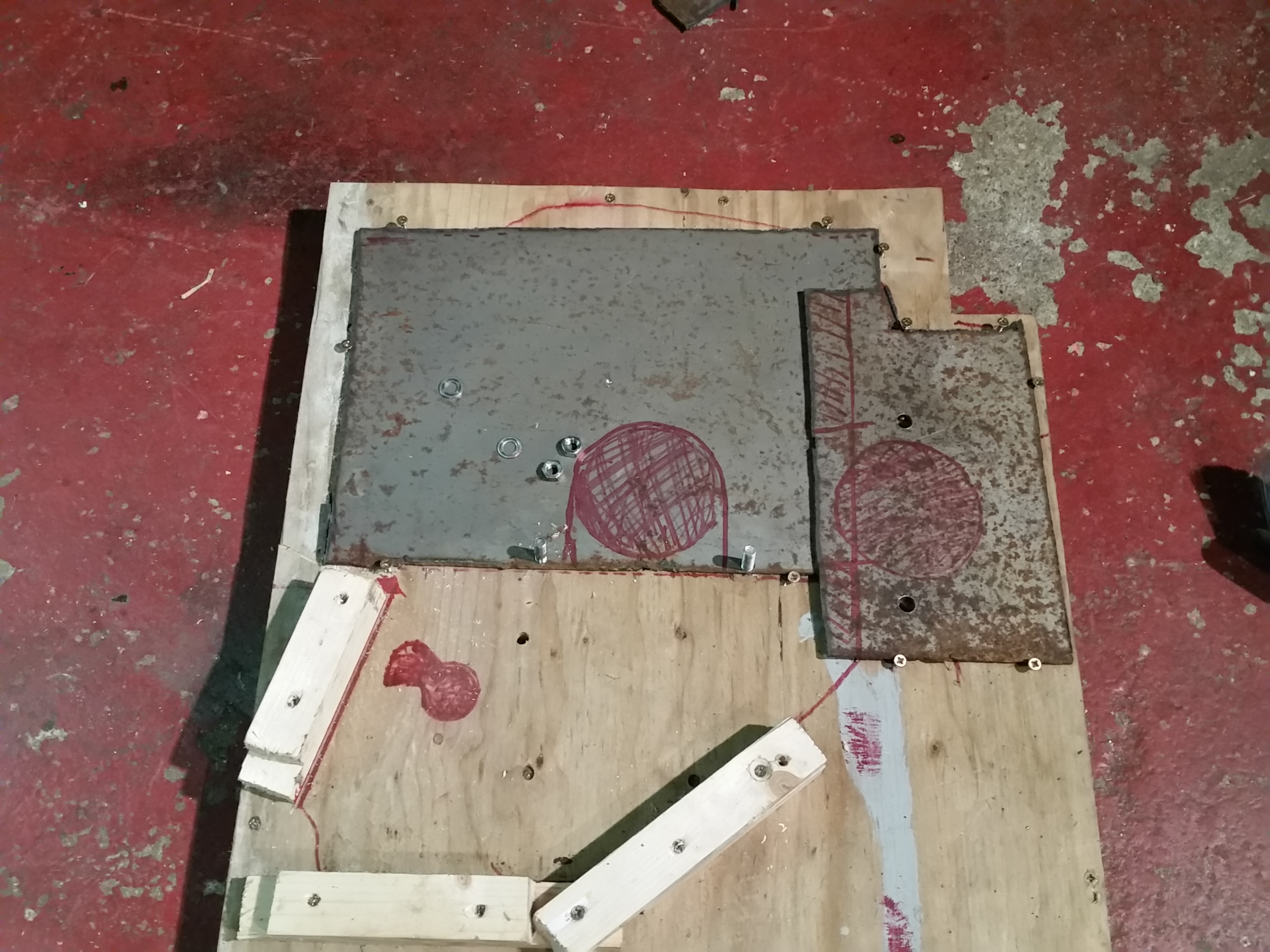
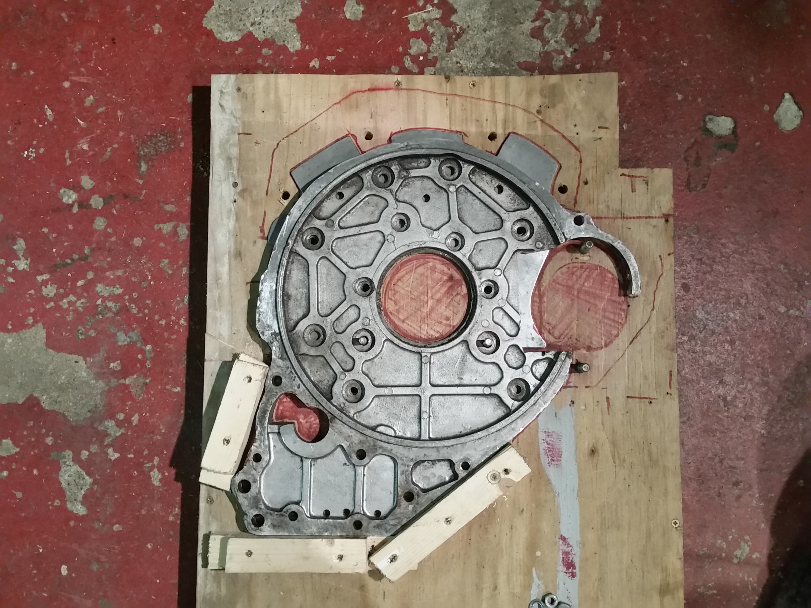
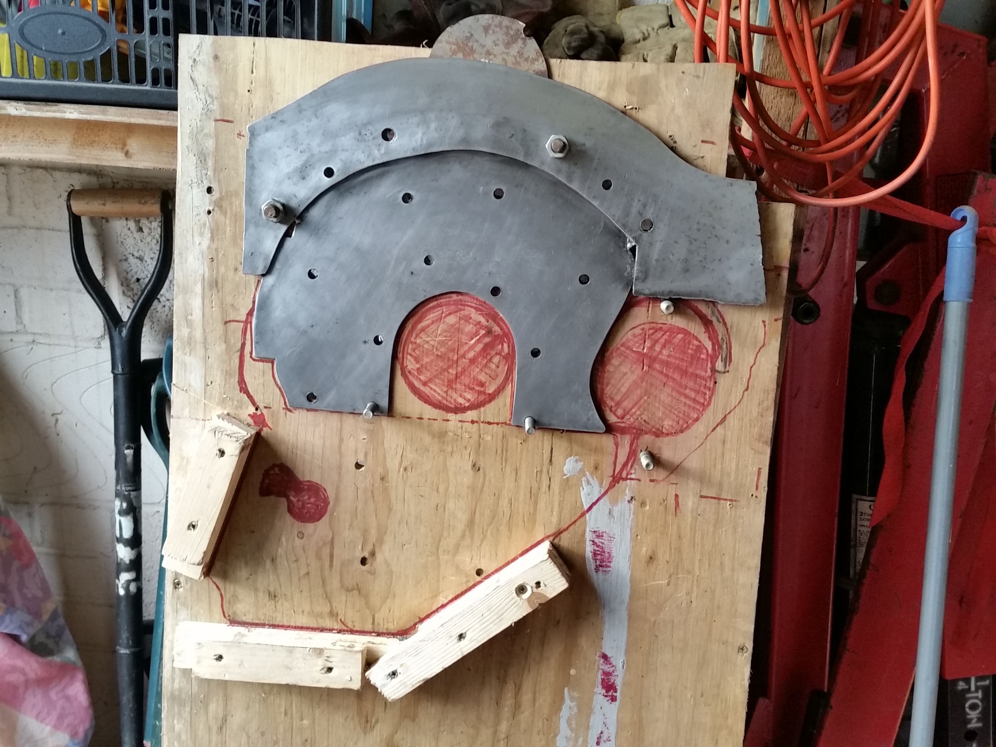
Build a jig for the backplate and the old, prototype plate (see, I called it
that again), and use this to make a new adapter from some slabs of 3mm steel.
(Any excuse to play with the plasma cutter!)
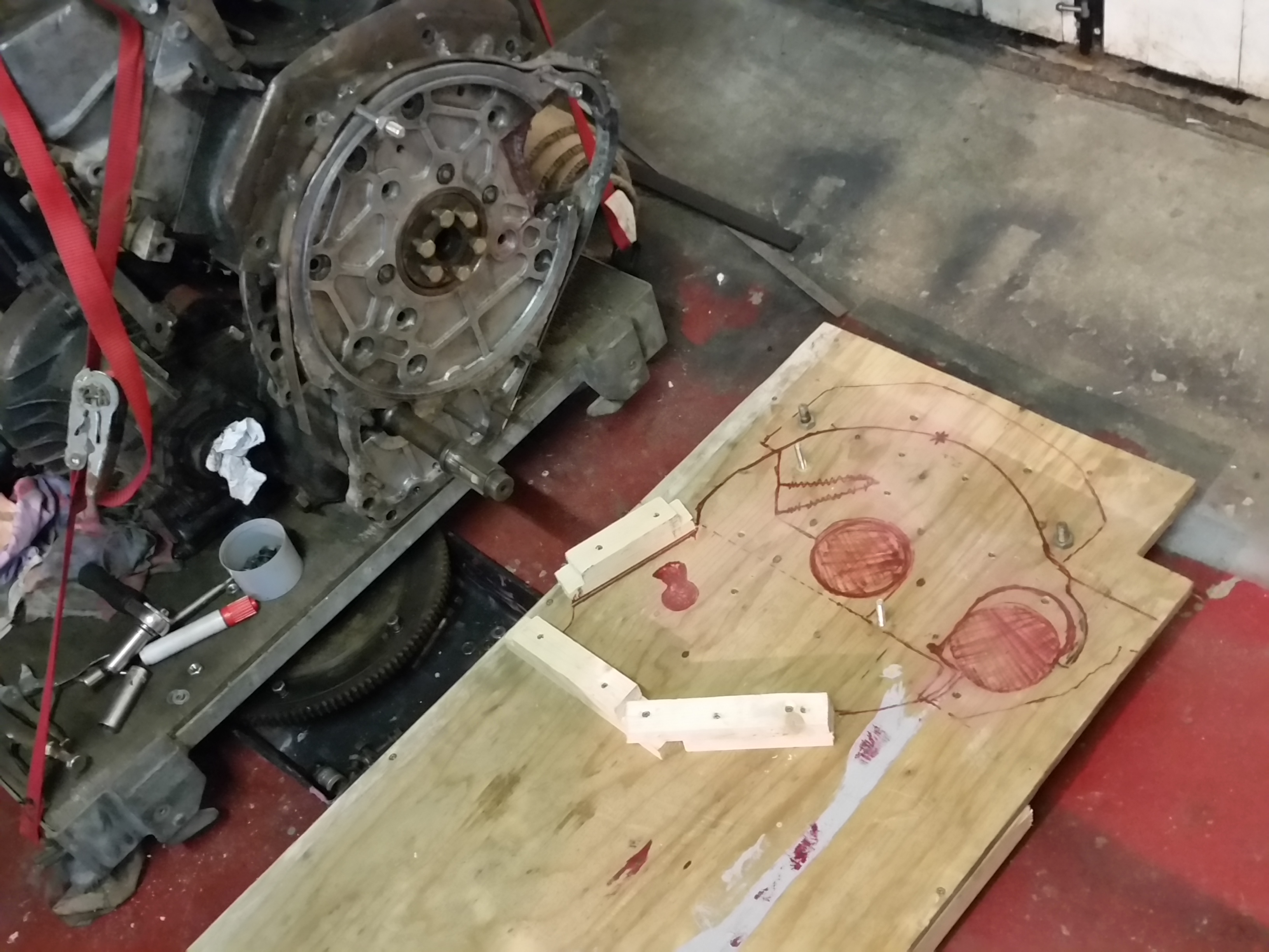
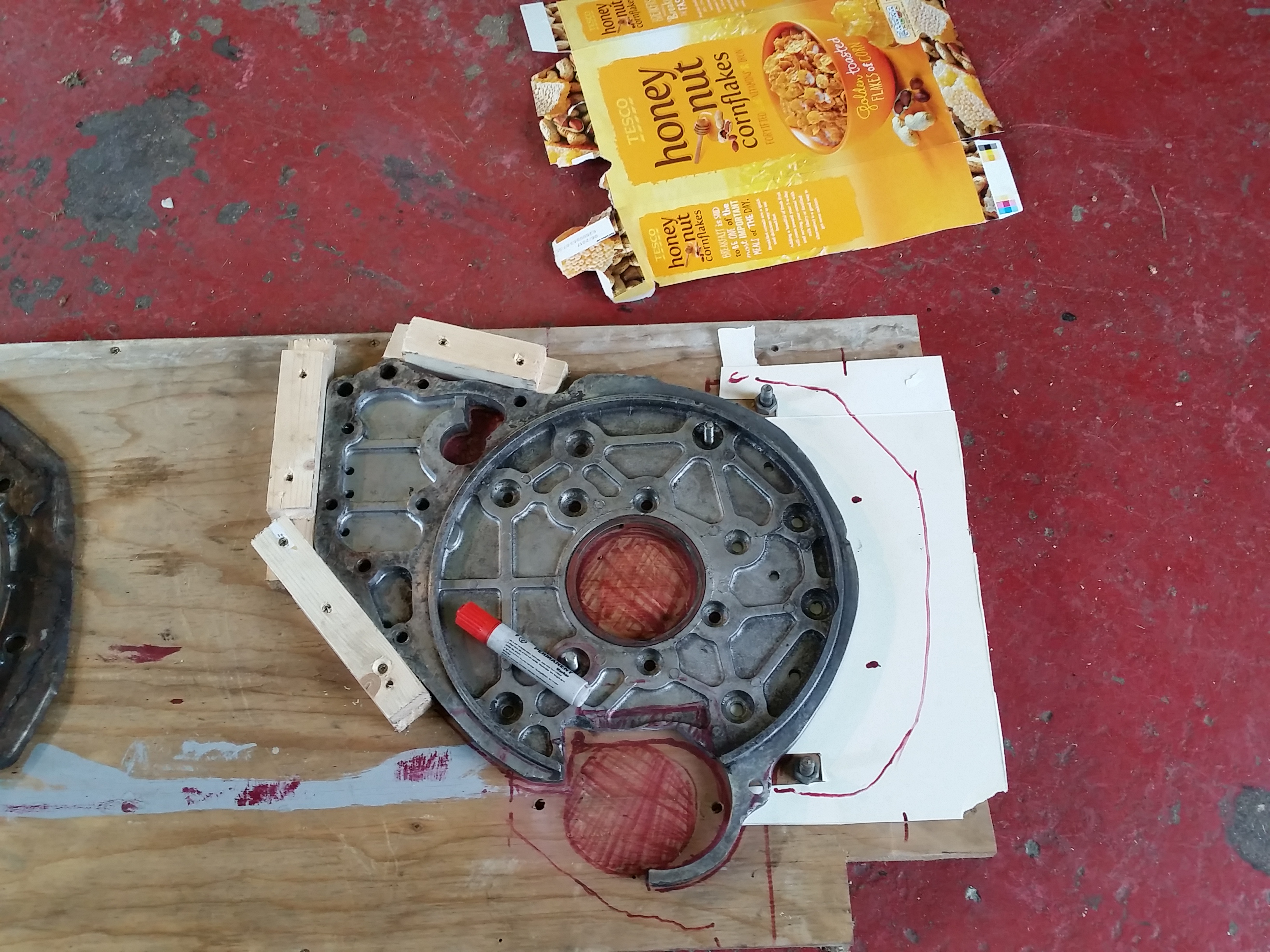
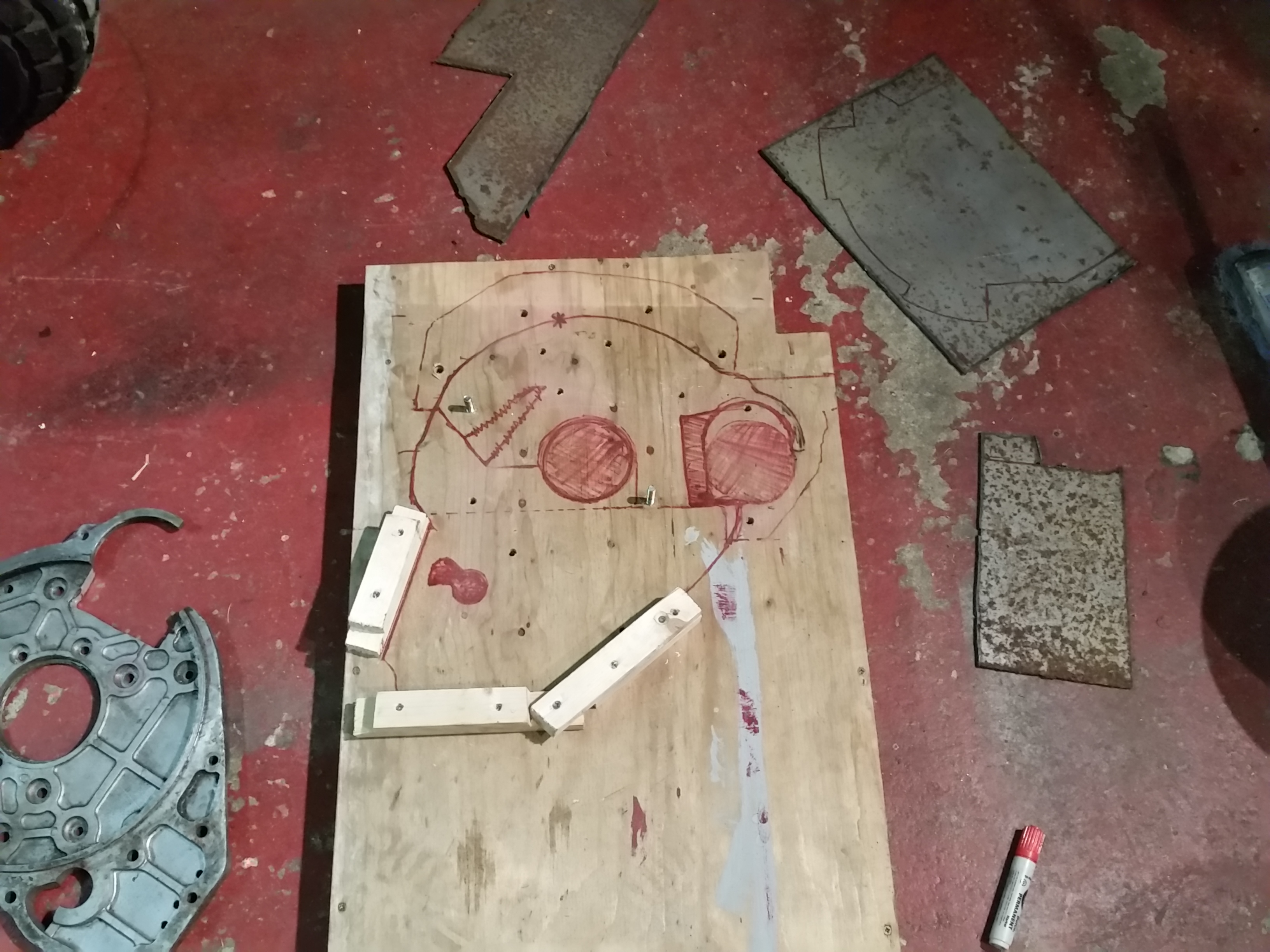
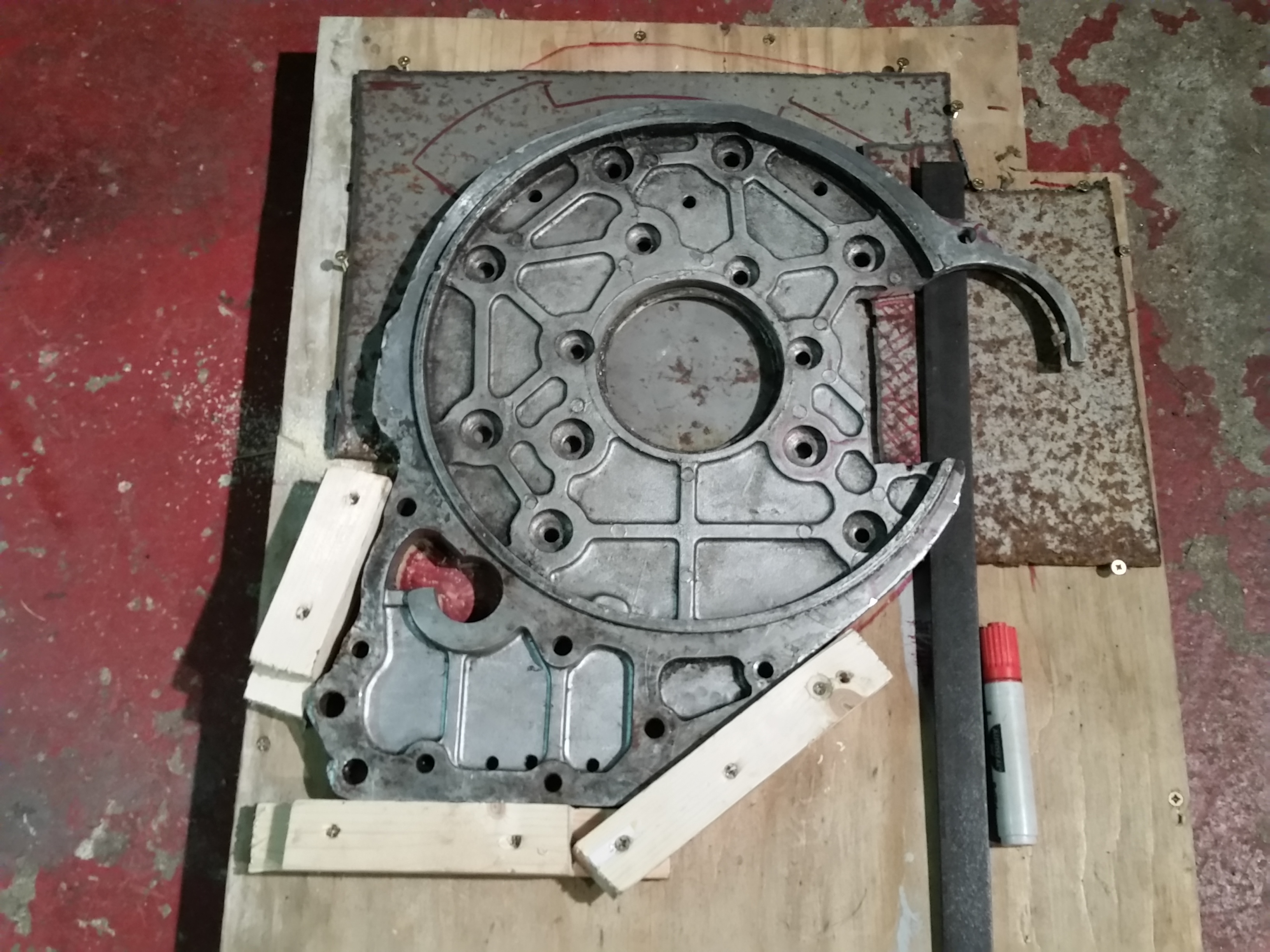
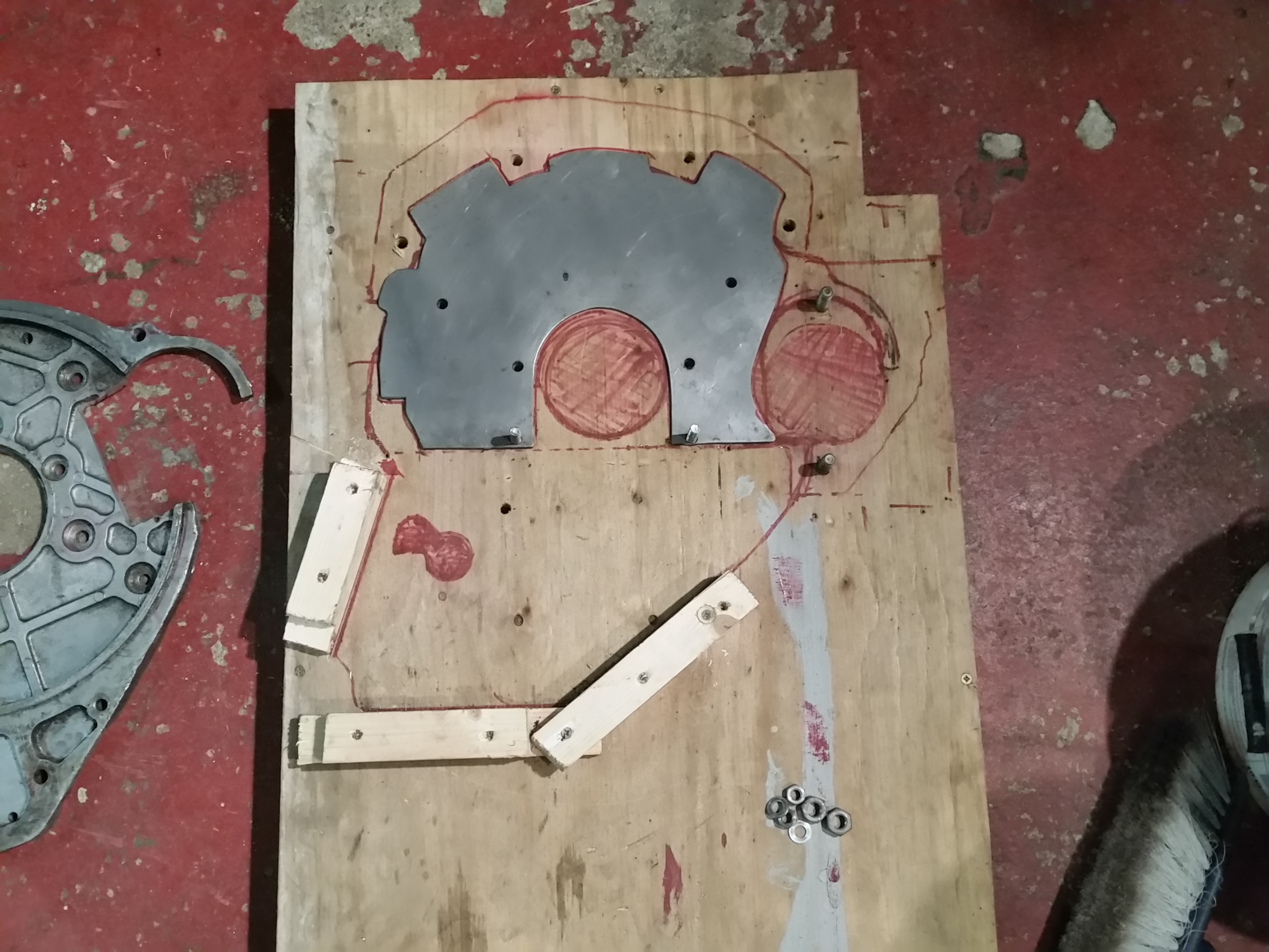
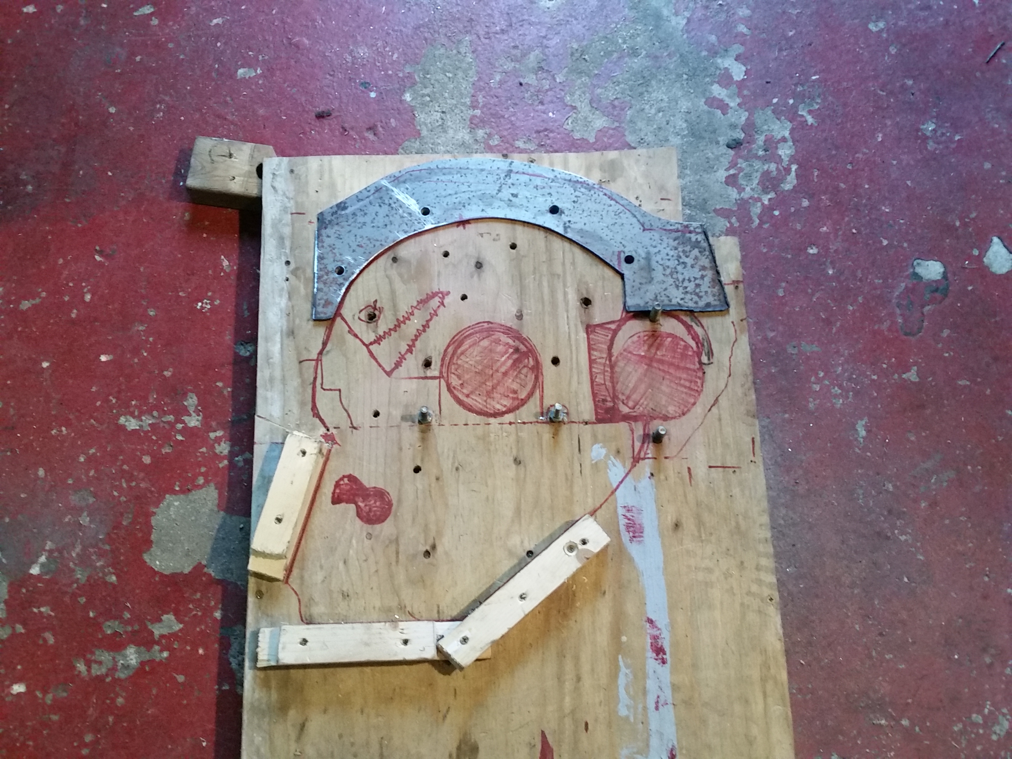
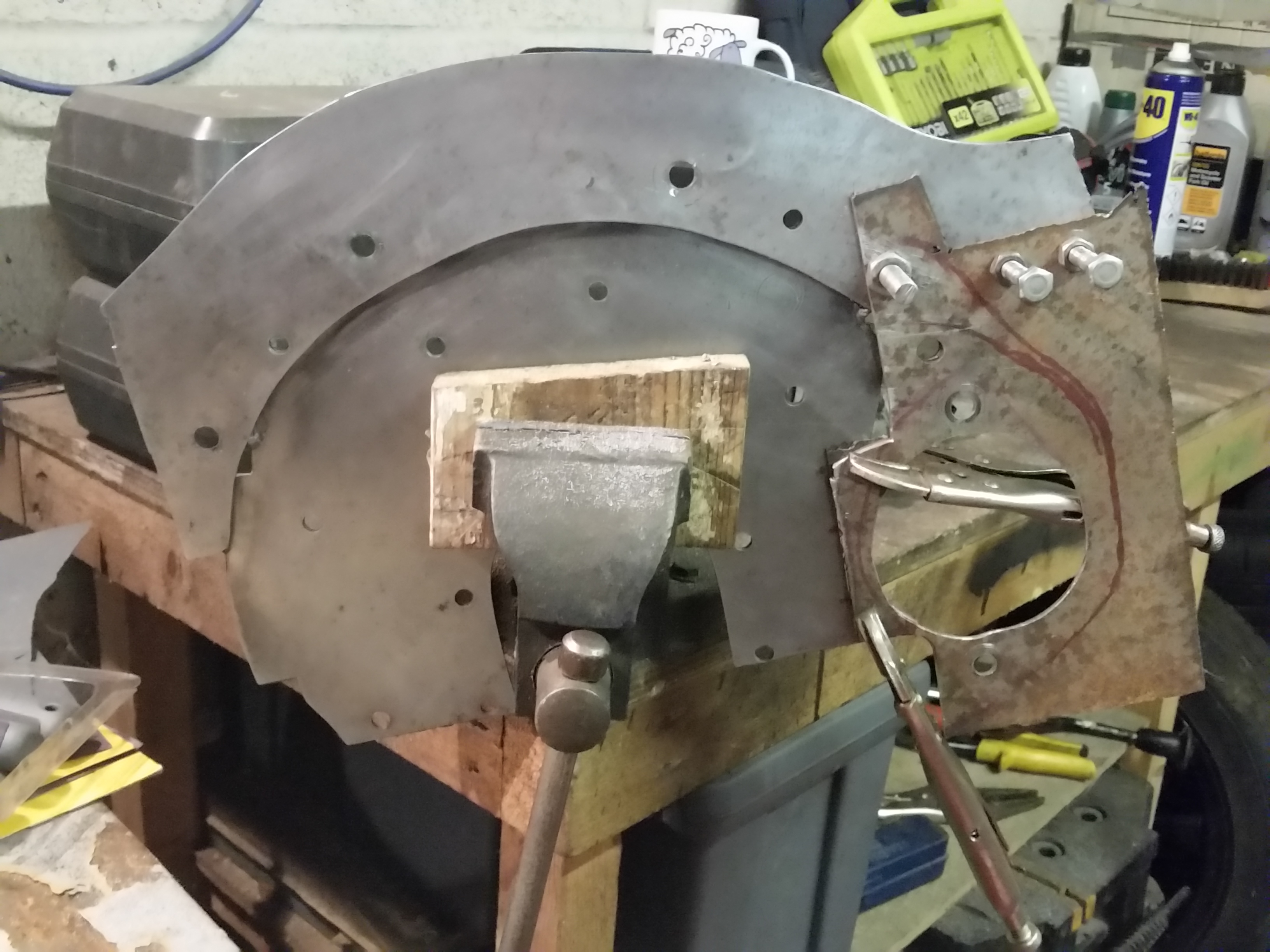
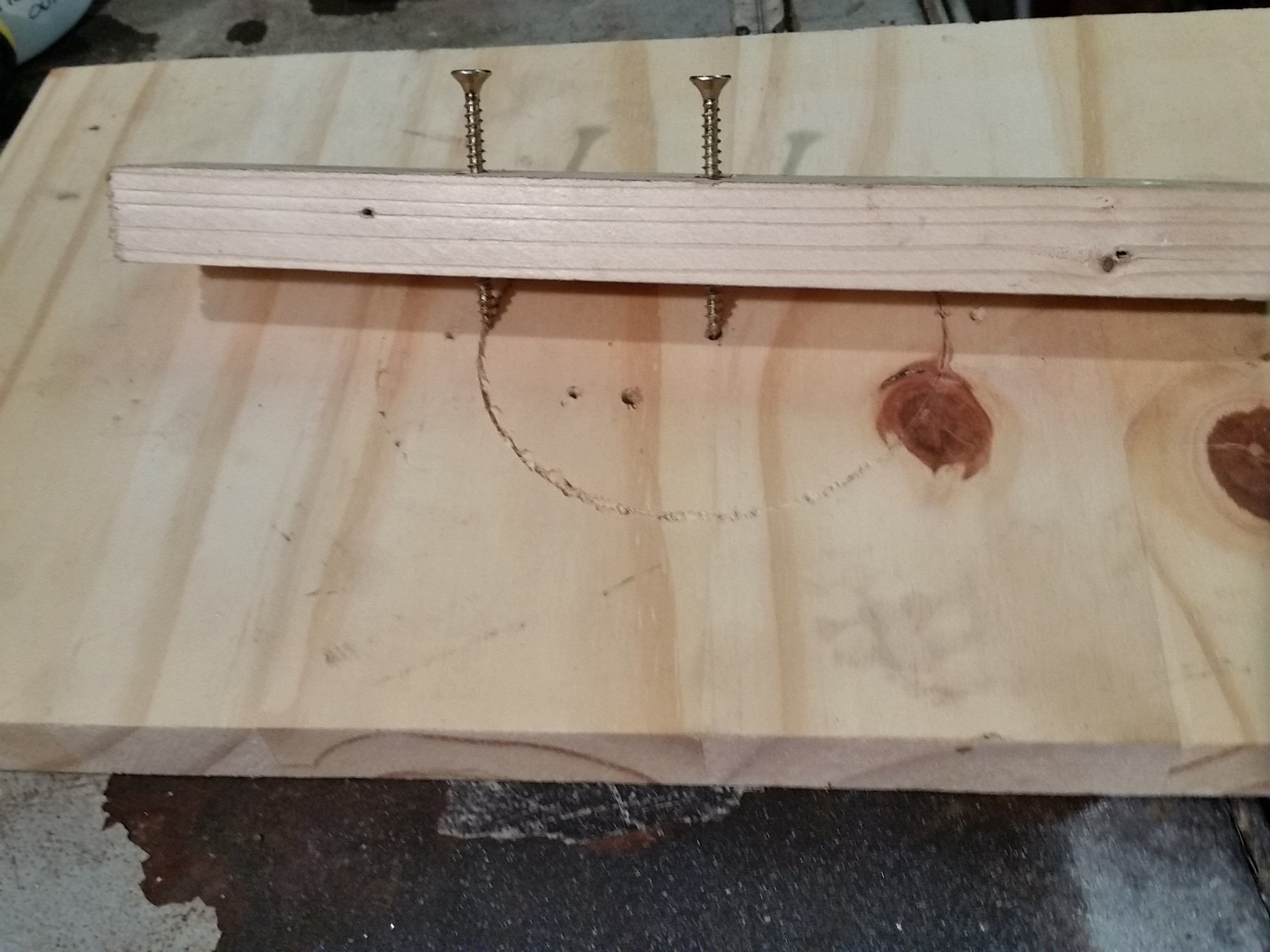
A solid bit of 18mm ply with a few discretely arranged blocks of wood will hold
things in place while a drill is run through all the bolt holes to properly
secure/locate things.
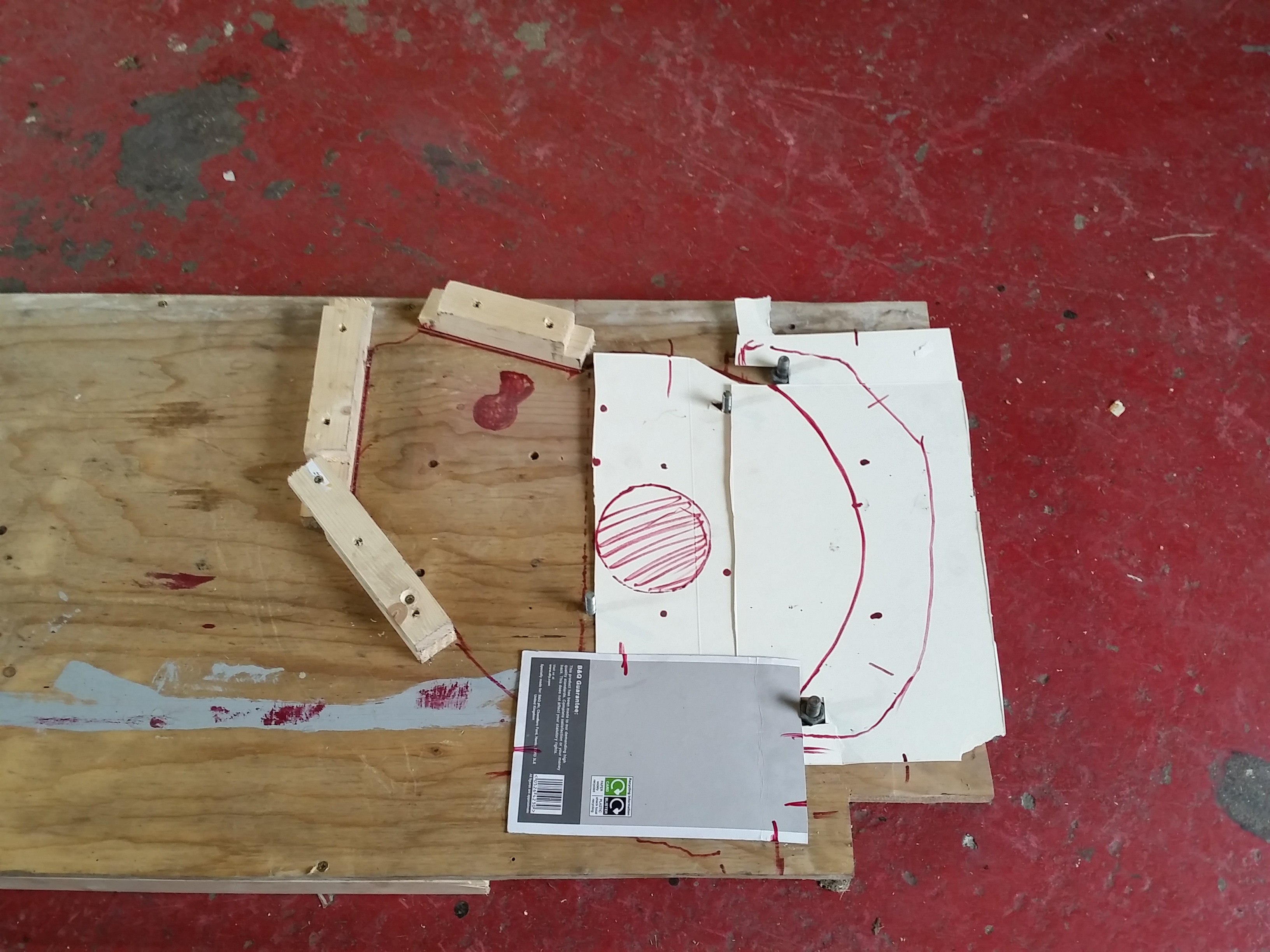
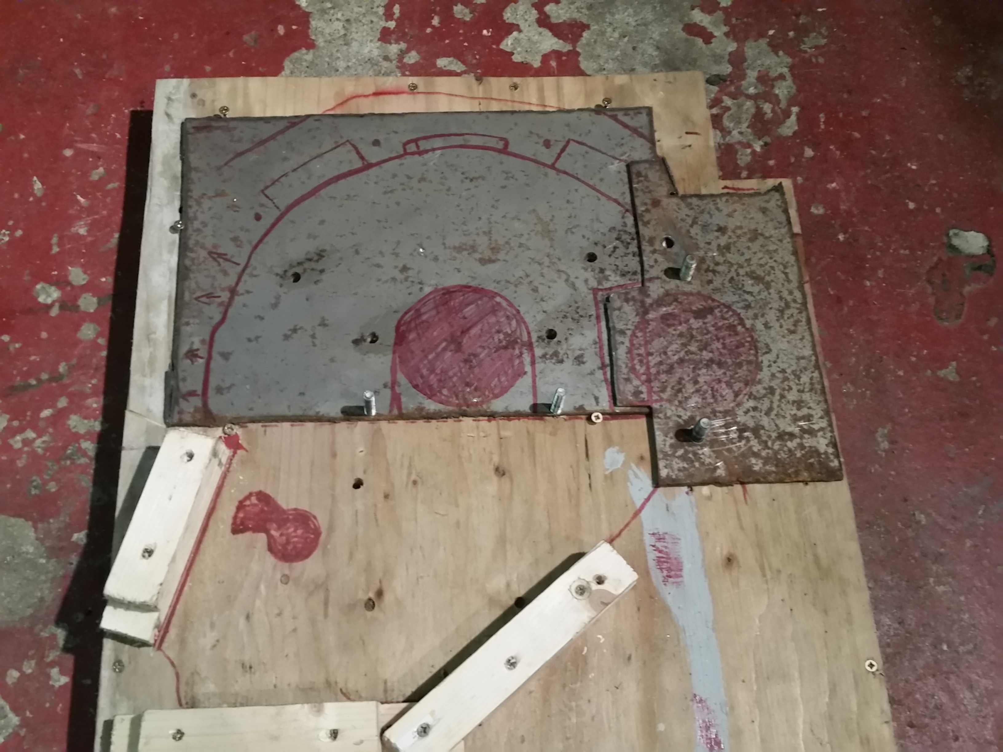
Then each of the existing bits can be drawn around for reference, and
approximate templates can be made from card, ready to transferring onto steel.
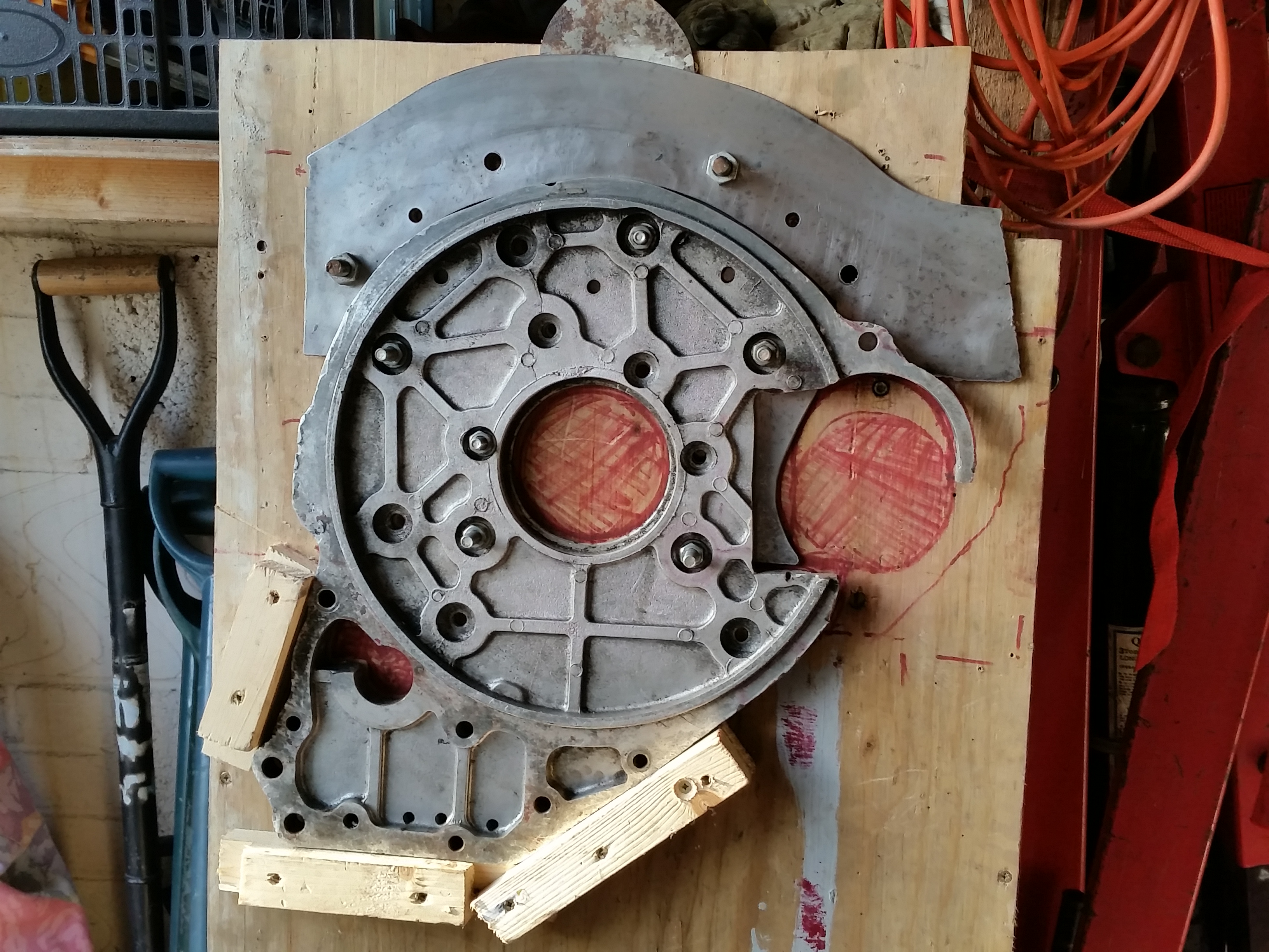
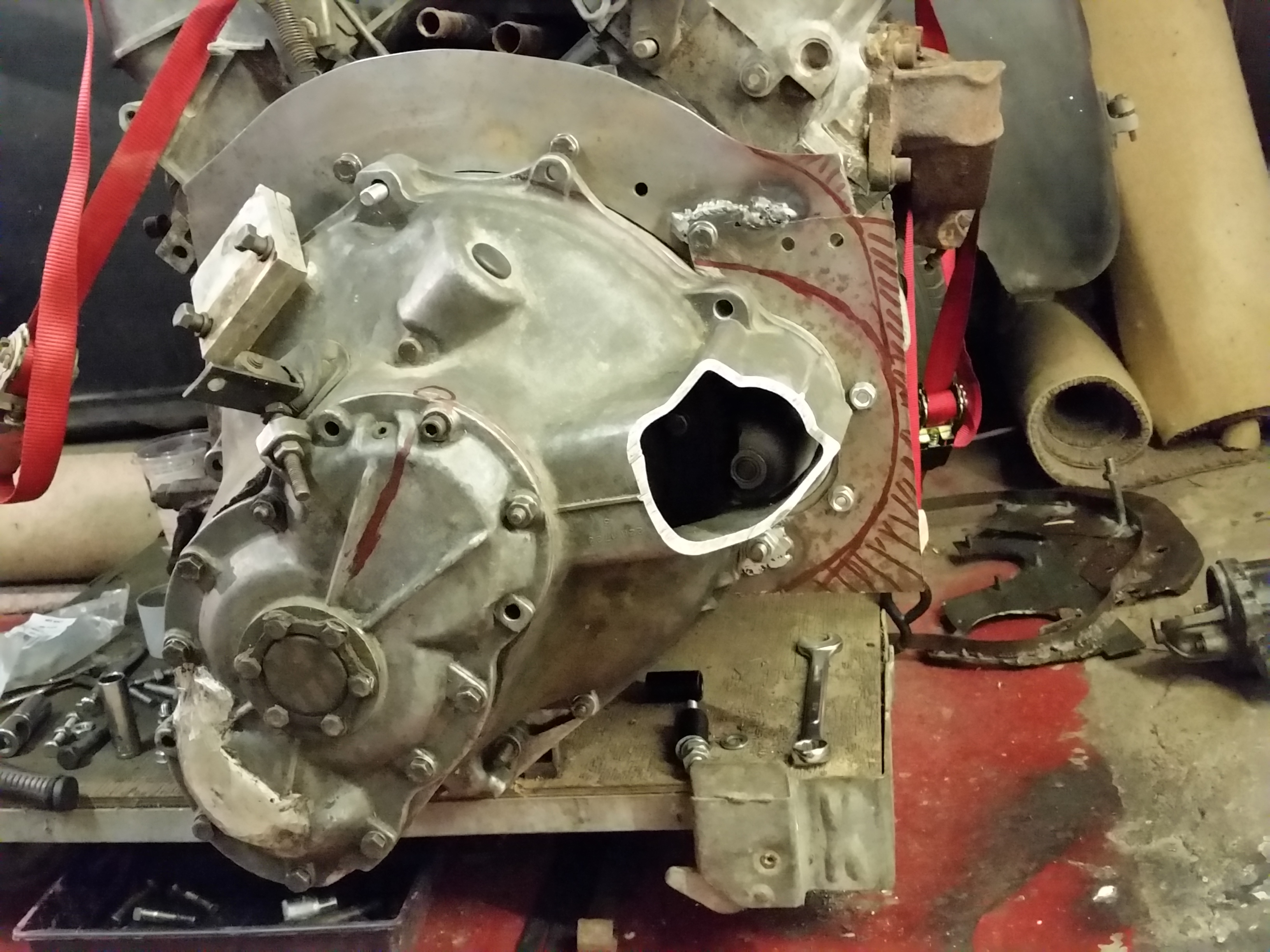
A slight bit of revision needed to the Princess backplate to allow the new
starter flange to sit further through and engage better with the flywheel.
Revised shape traced onto steel, and chopped for a trial fit.
All seems to line up when suitably spaced, so should be a simple job to weld it
against the adapter plate when everything is lined up.
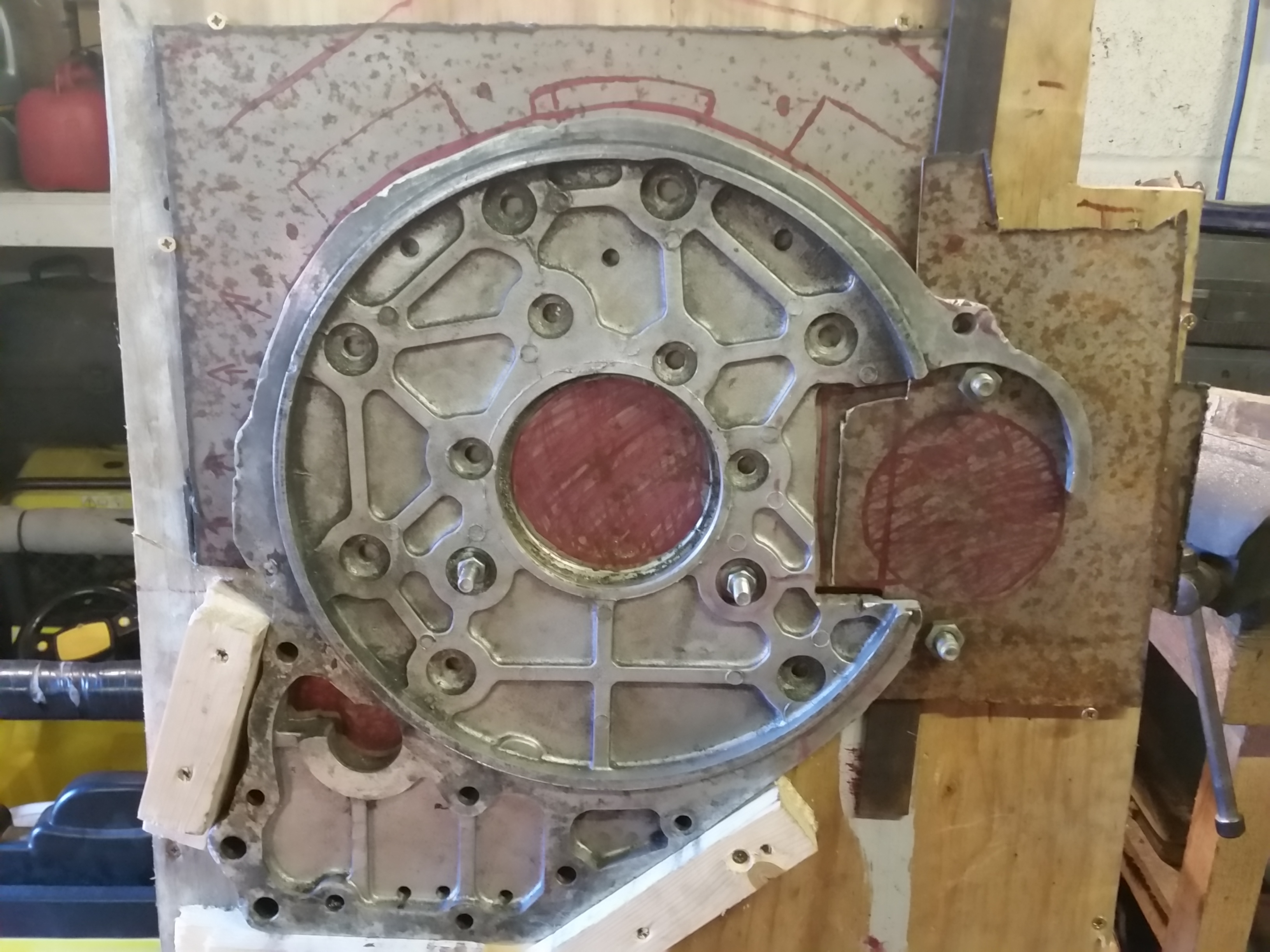
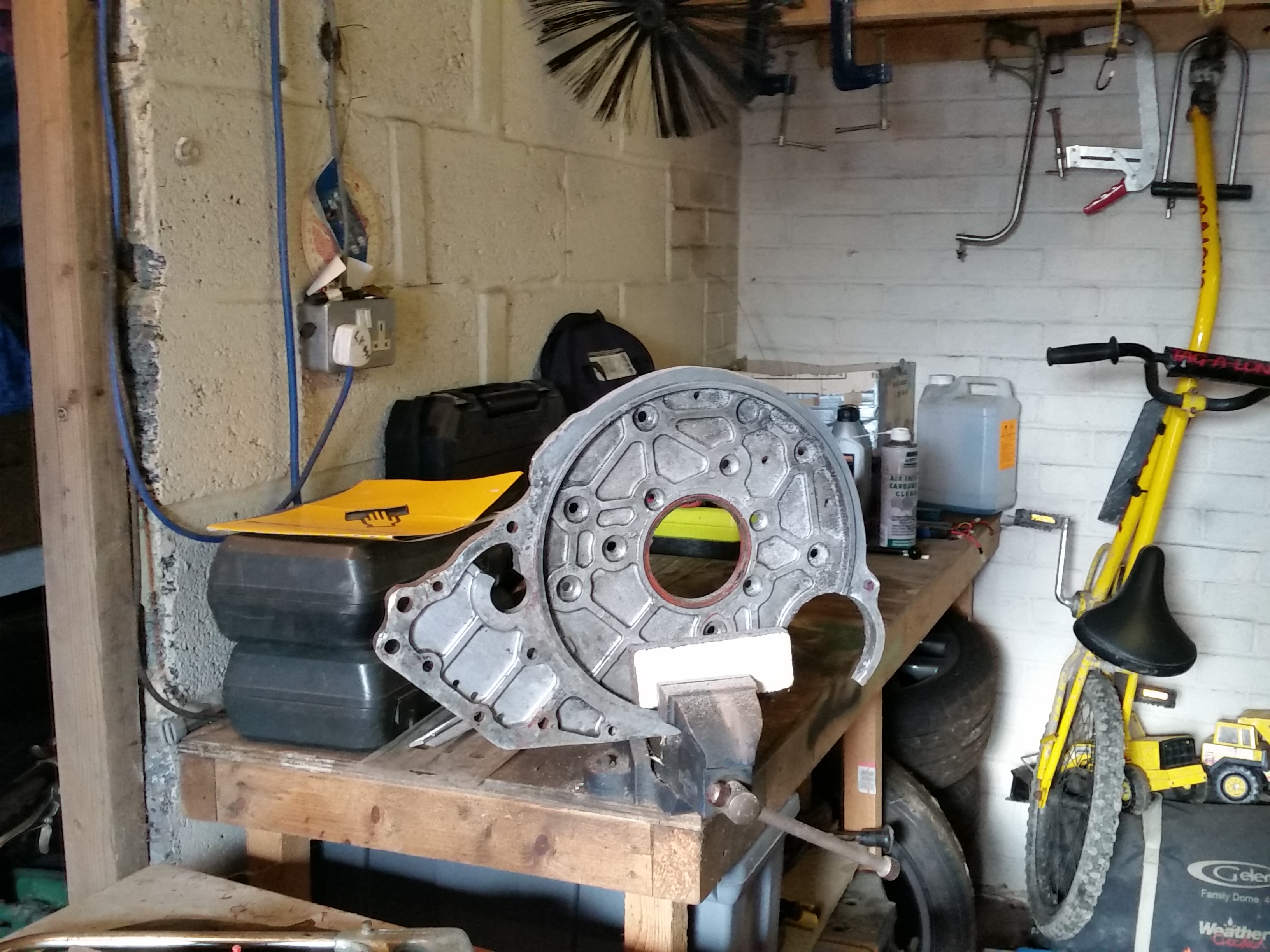
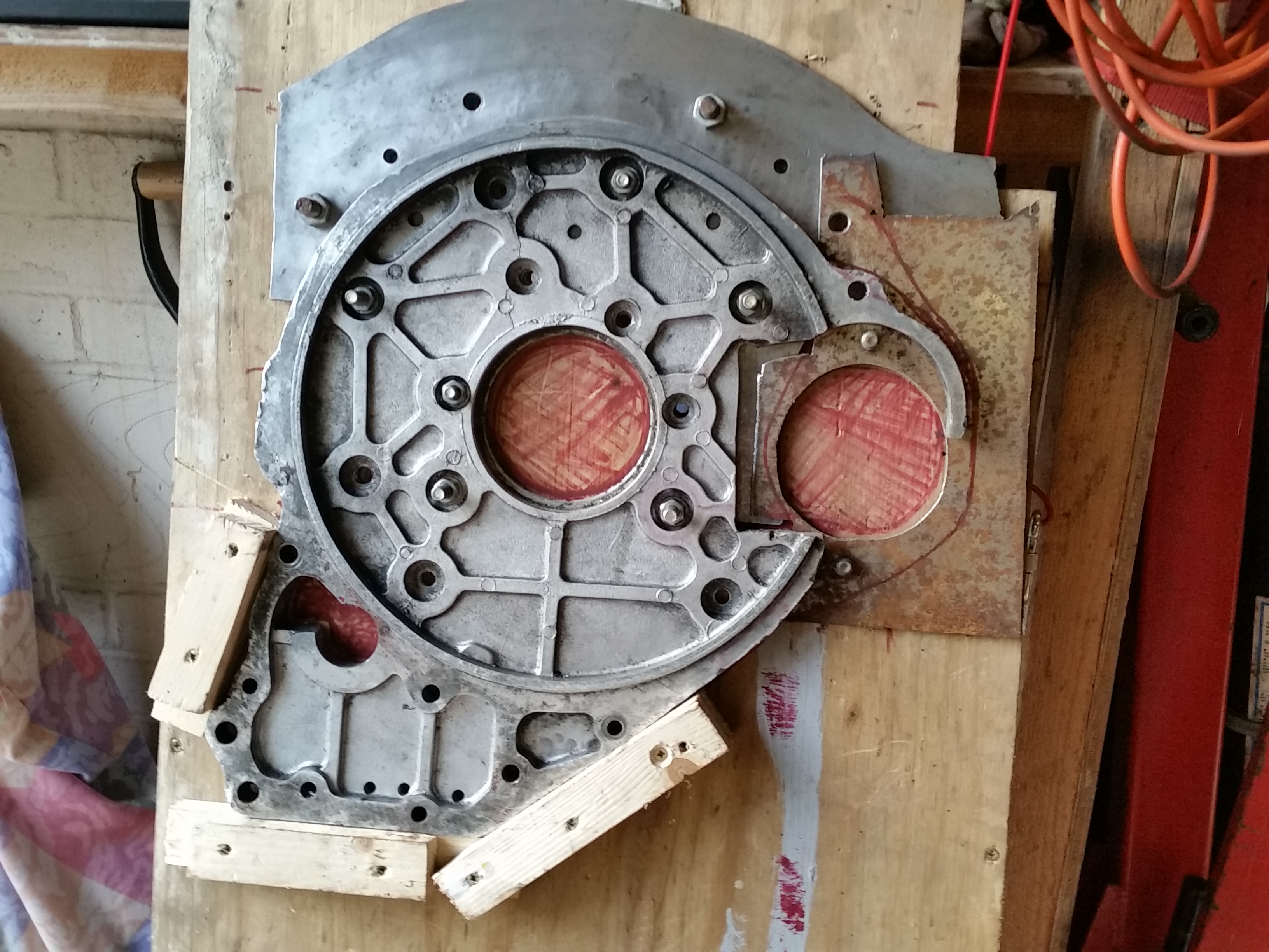
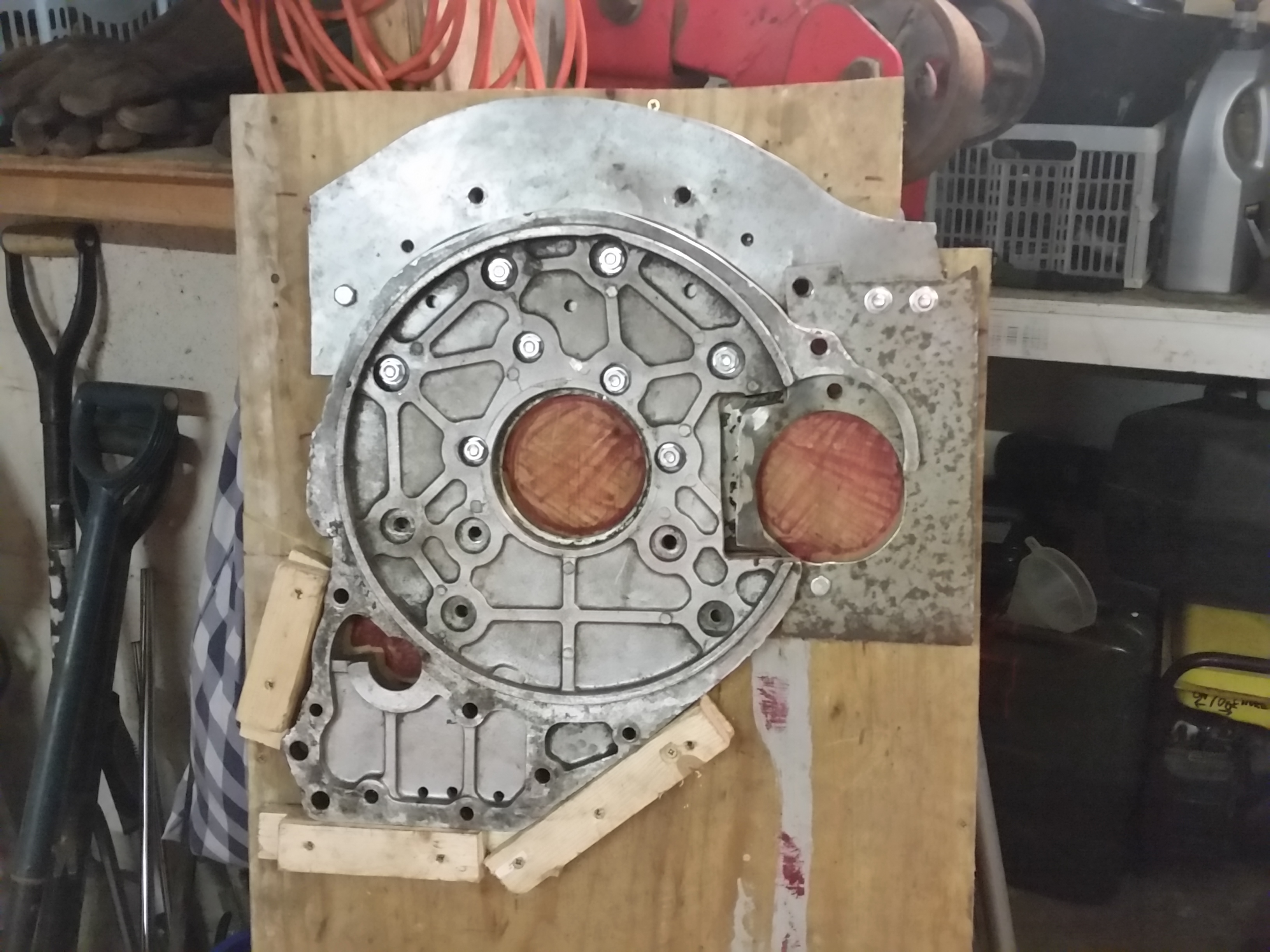
The first plate cut to shape and trial fitted.
Precision engineering using the jig to drill the holes for the engine bolts,
allowing it to be fitted, scribbled on, and shaped to fit.
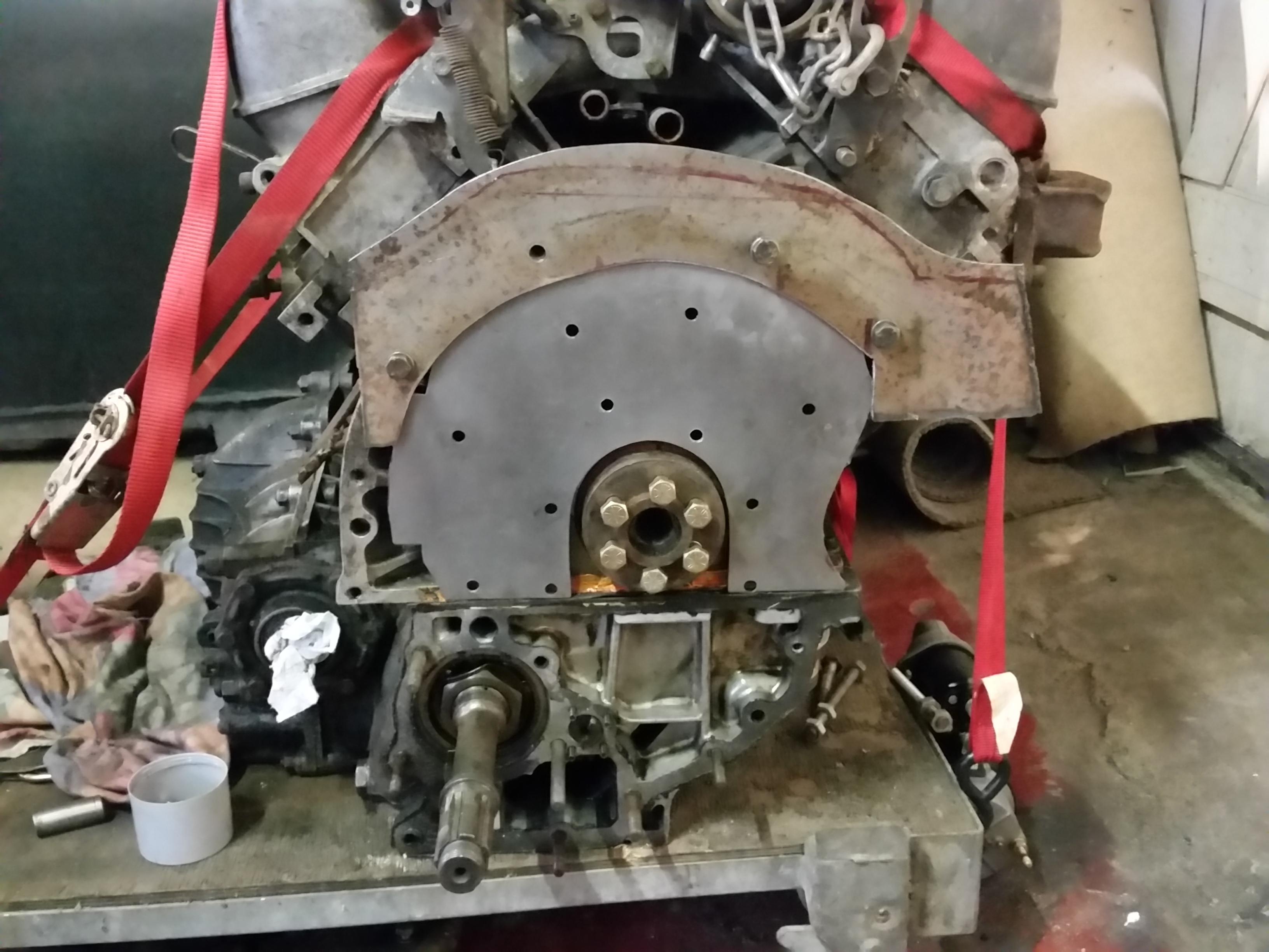
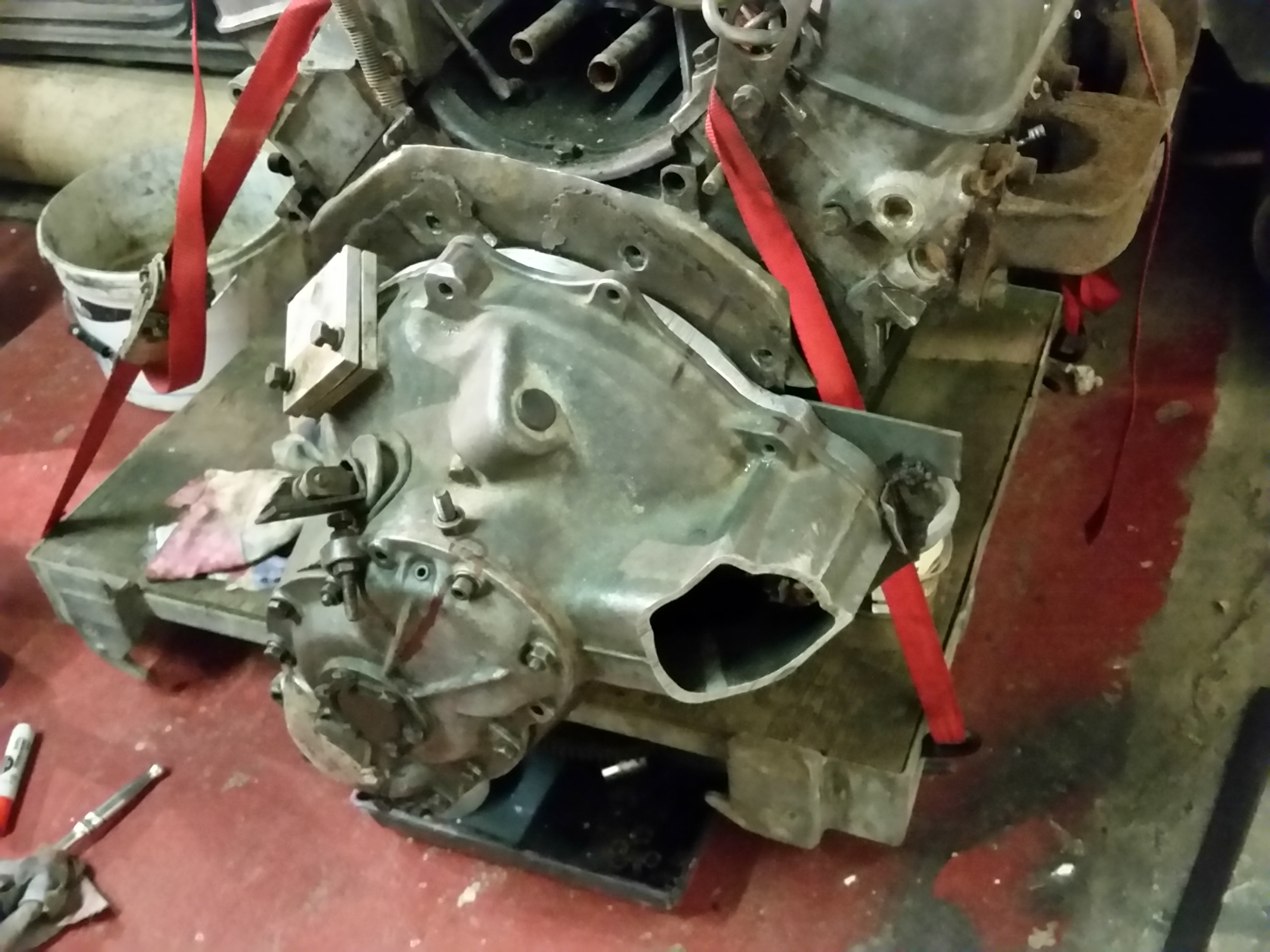
With a rough flange for the starter in place, it looks like it could almost
be a working plan...
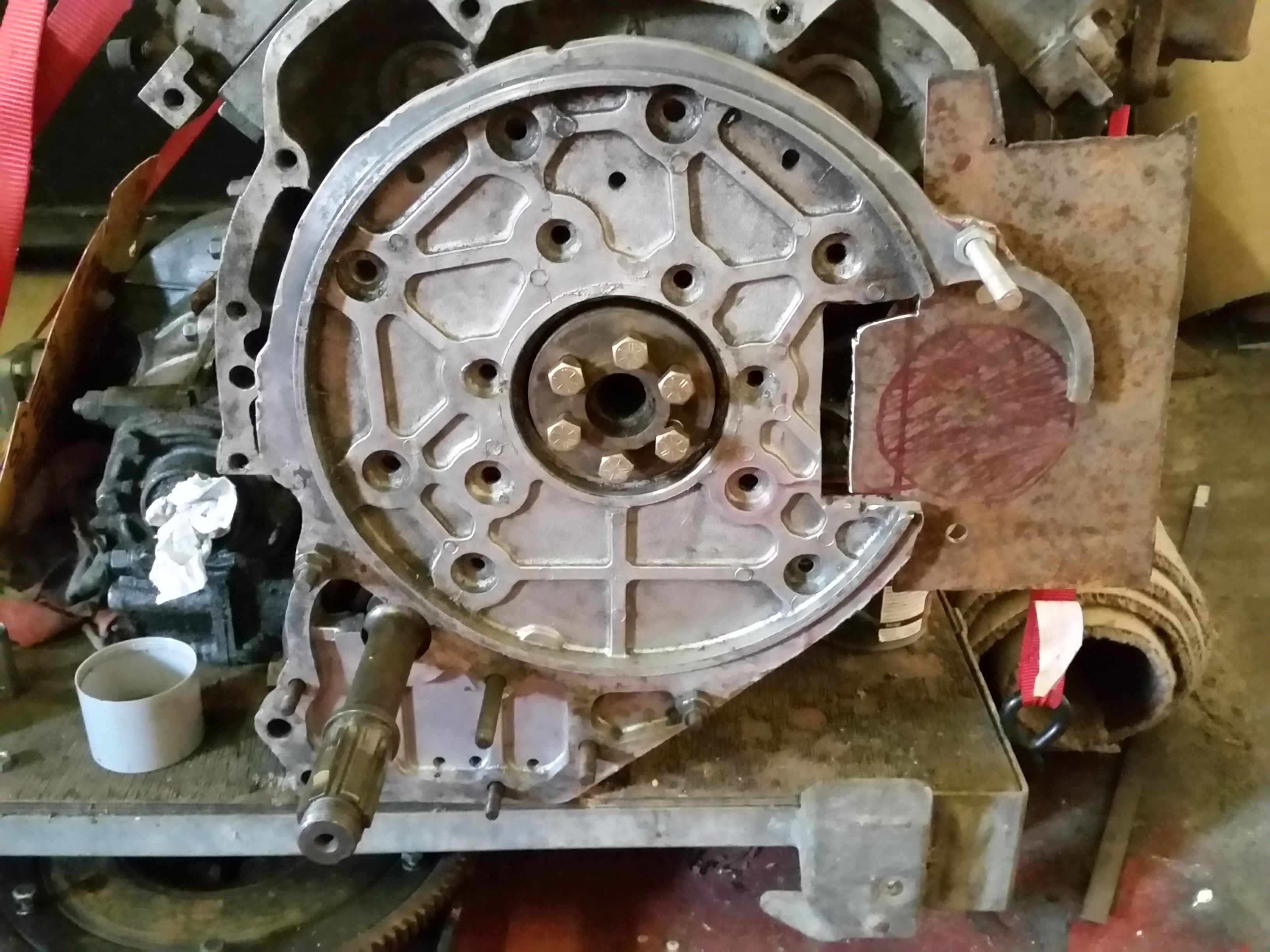
But always sensible to get someone else to check things fit properly!
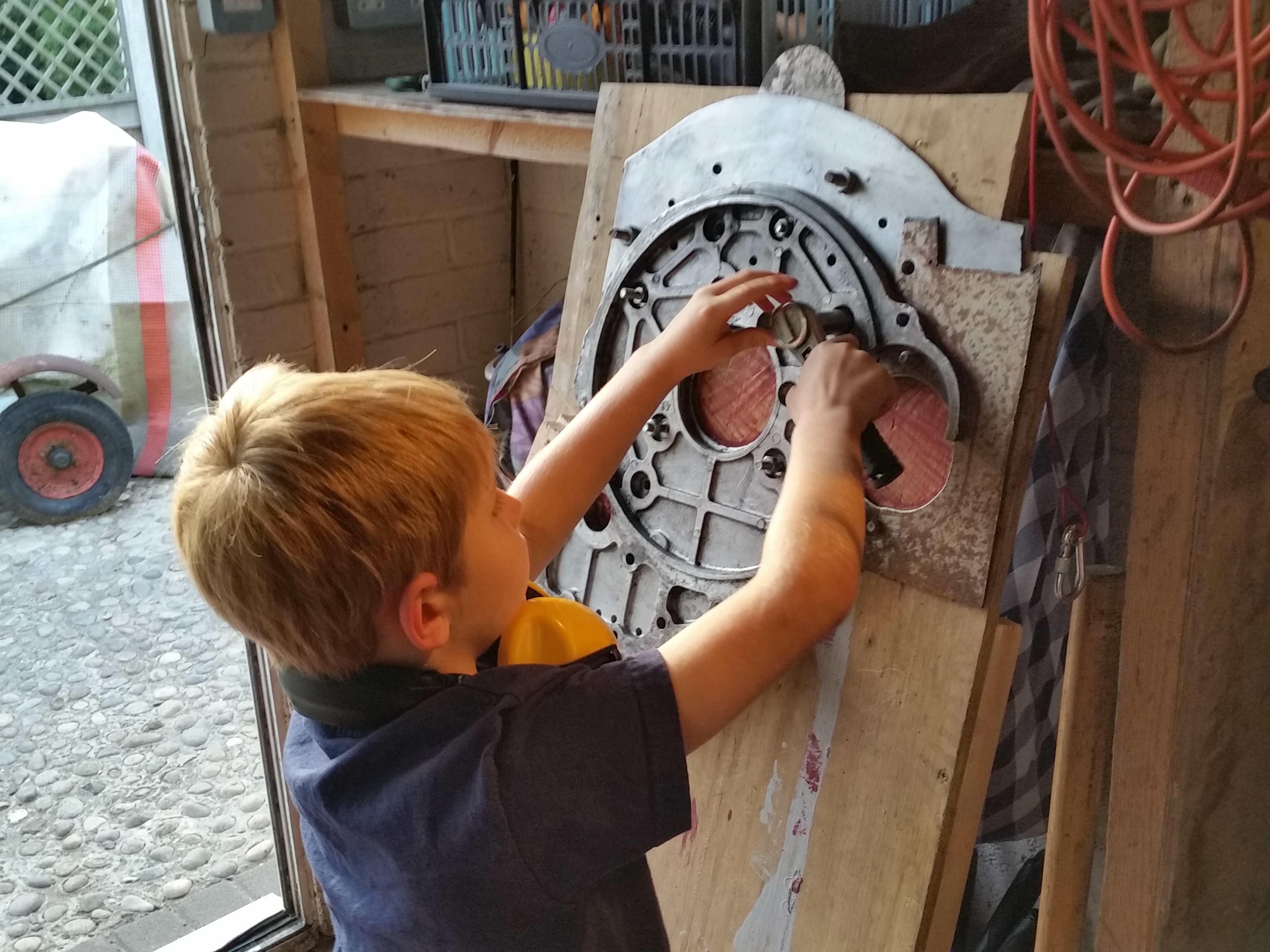
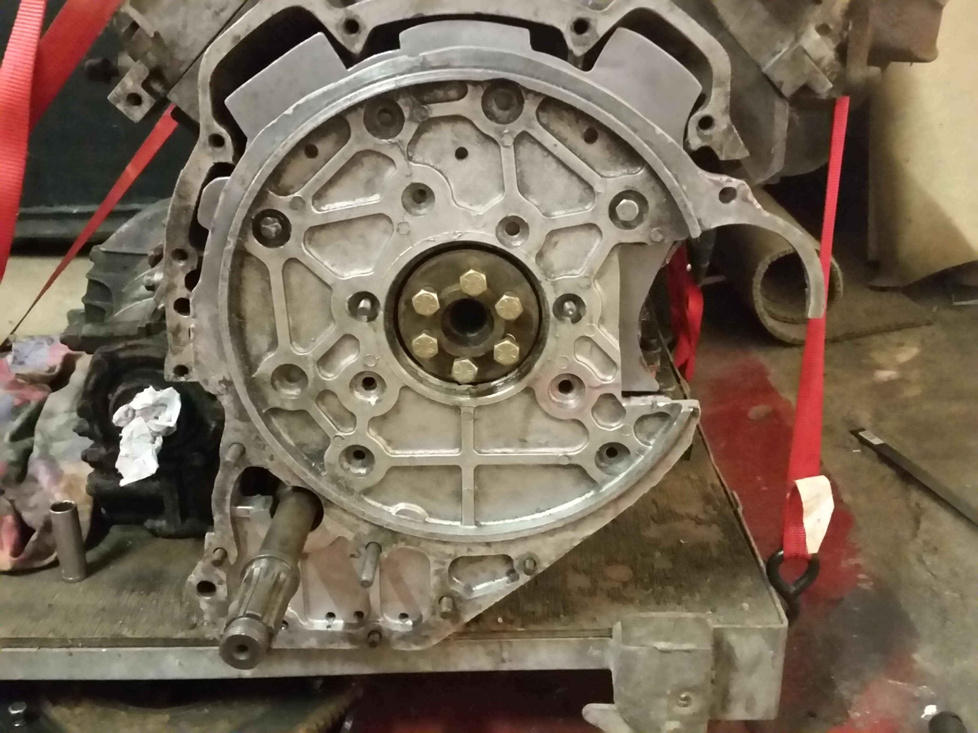
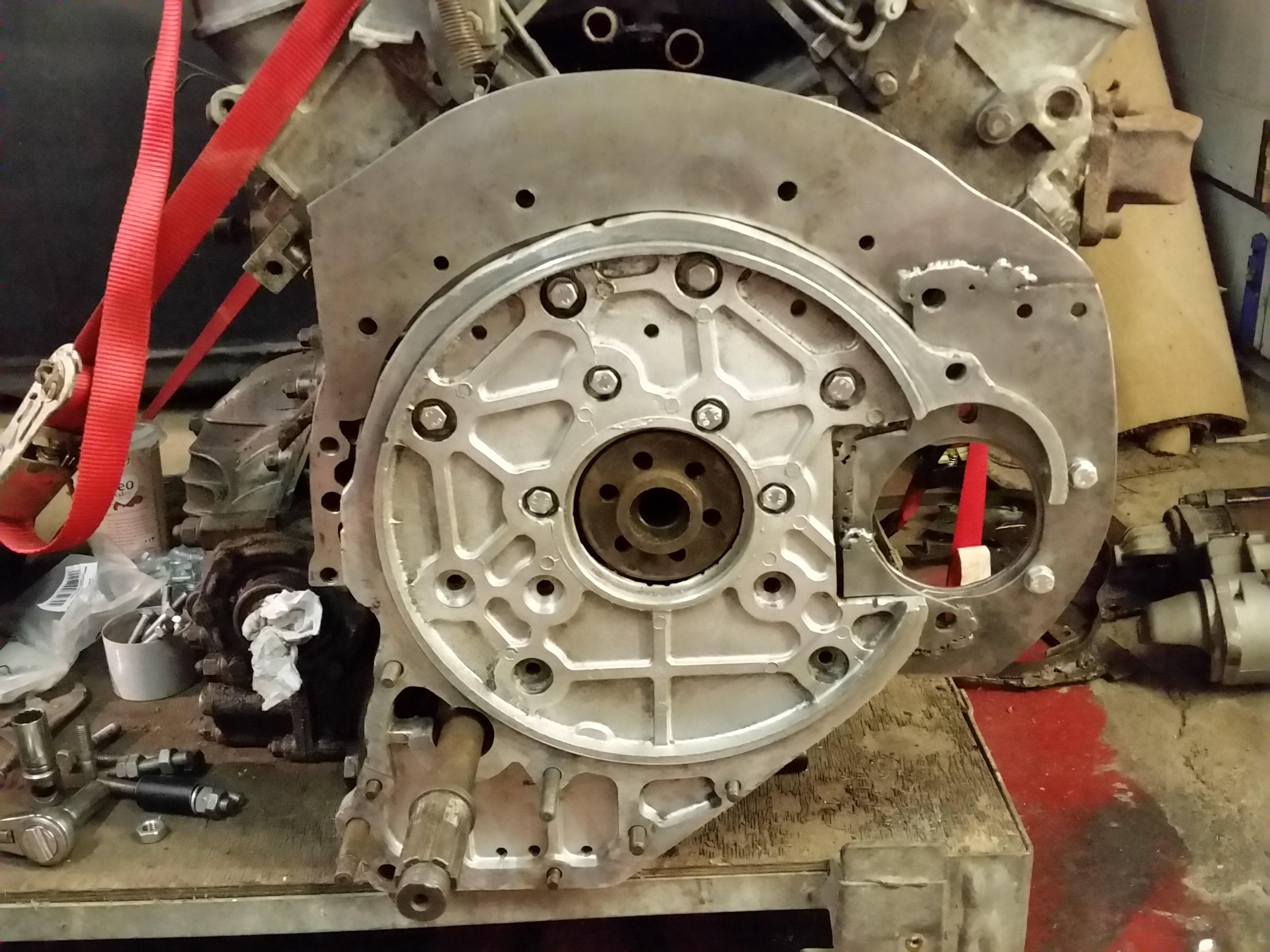
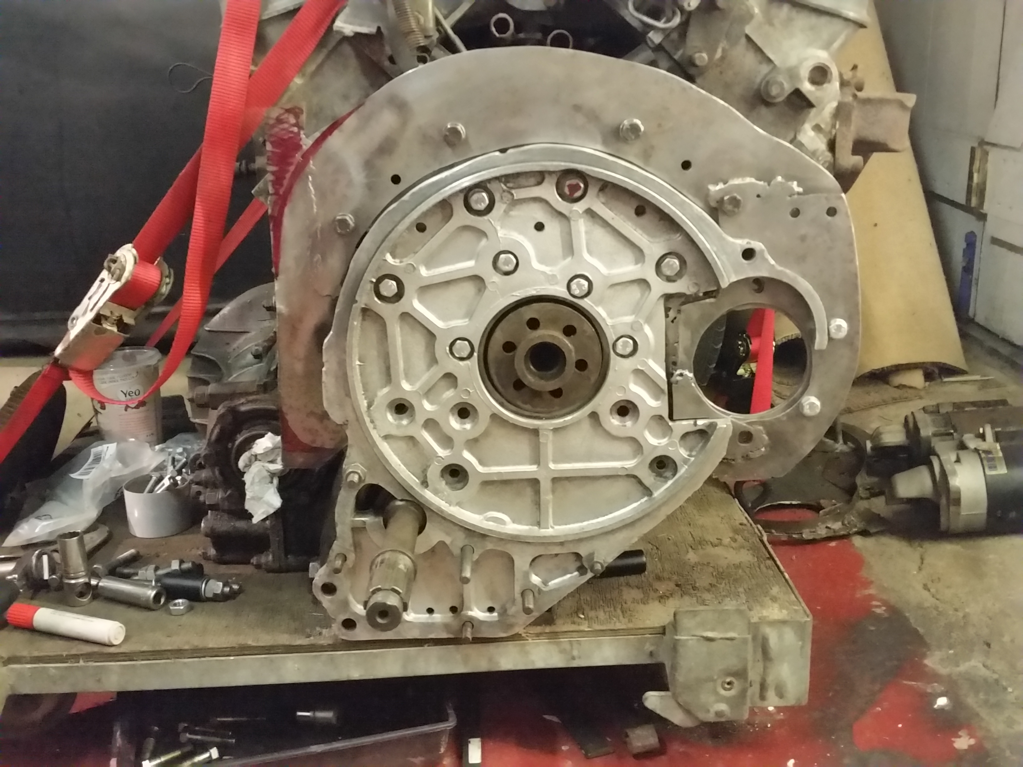
Starter tooth engagement with the flywheel looking far better with the new adapter, using temporary washers on the mount bolts to set the starter to the right depth, so the plates are bolted together to maintain alignment.
Back off the engine the plates are glued together, and at this point all the
holes should still be in the right place.
A bit more marking and trimming of the backplate.
I think maybe a small extension would tidy up the back edge, so may as well make
another bit while I'm here. Draw it trim it, clamp it weld it...
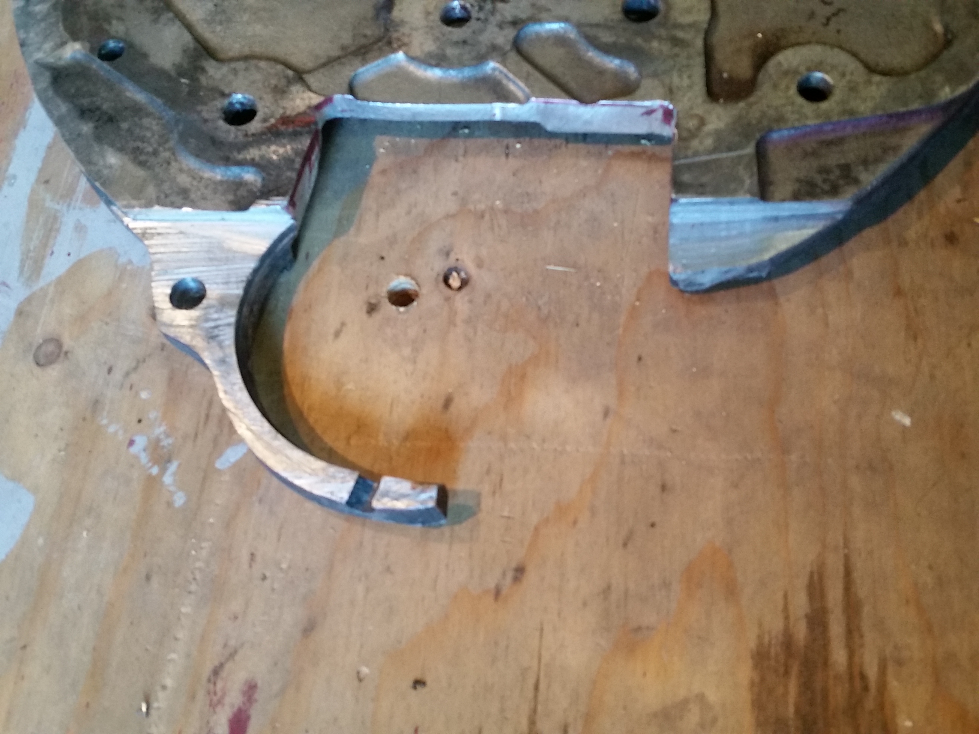
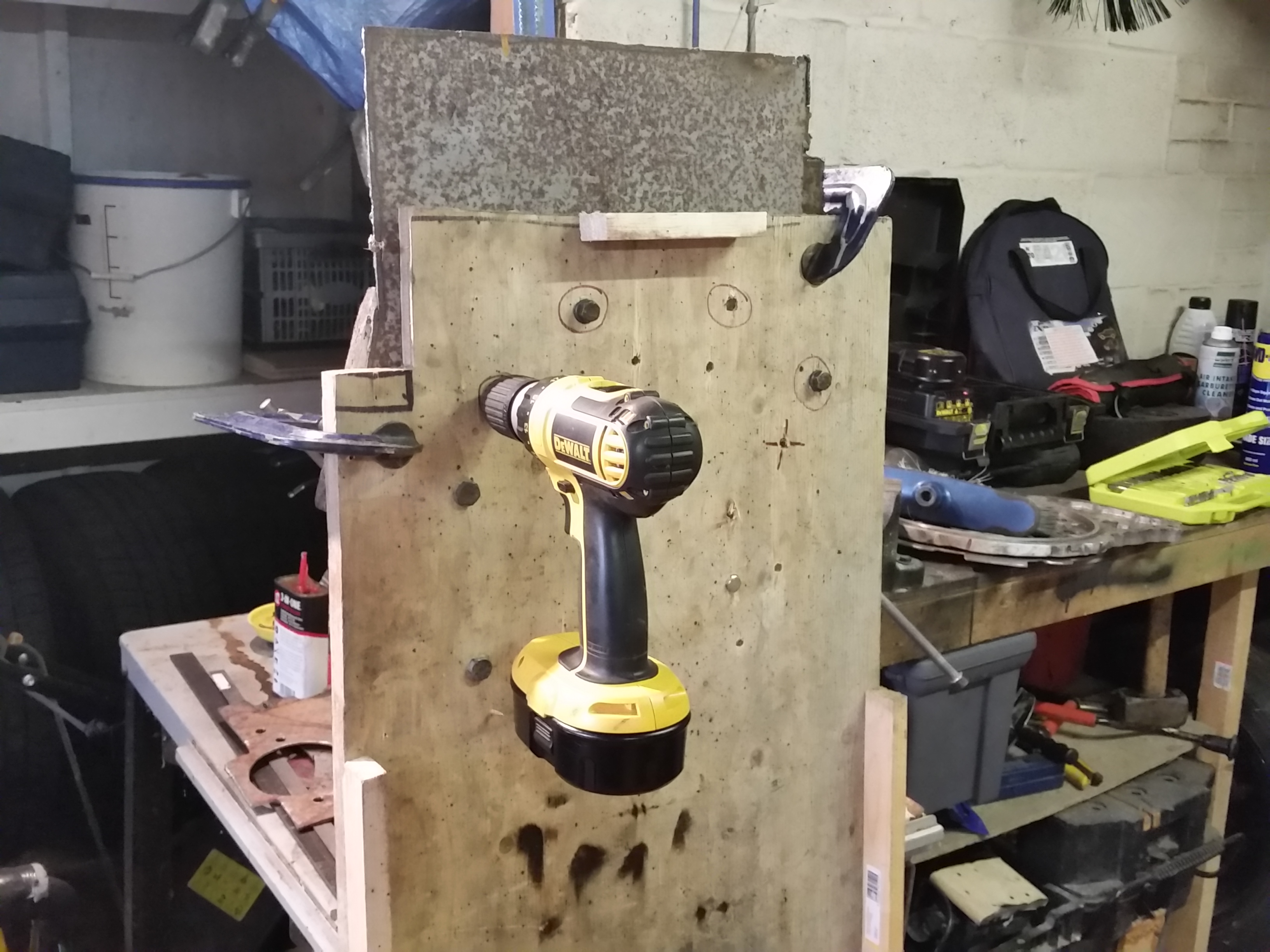
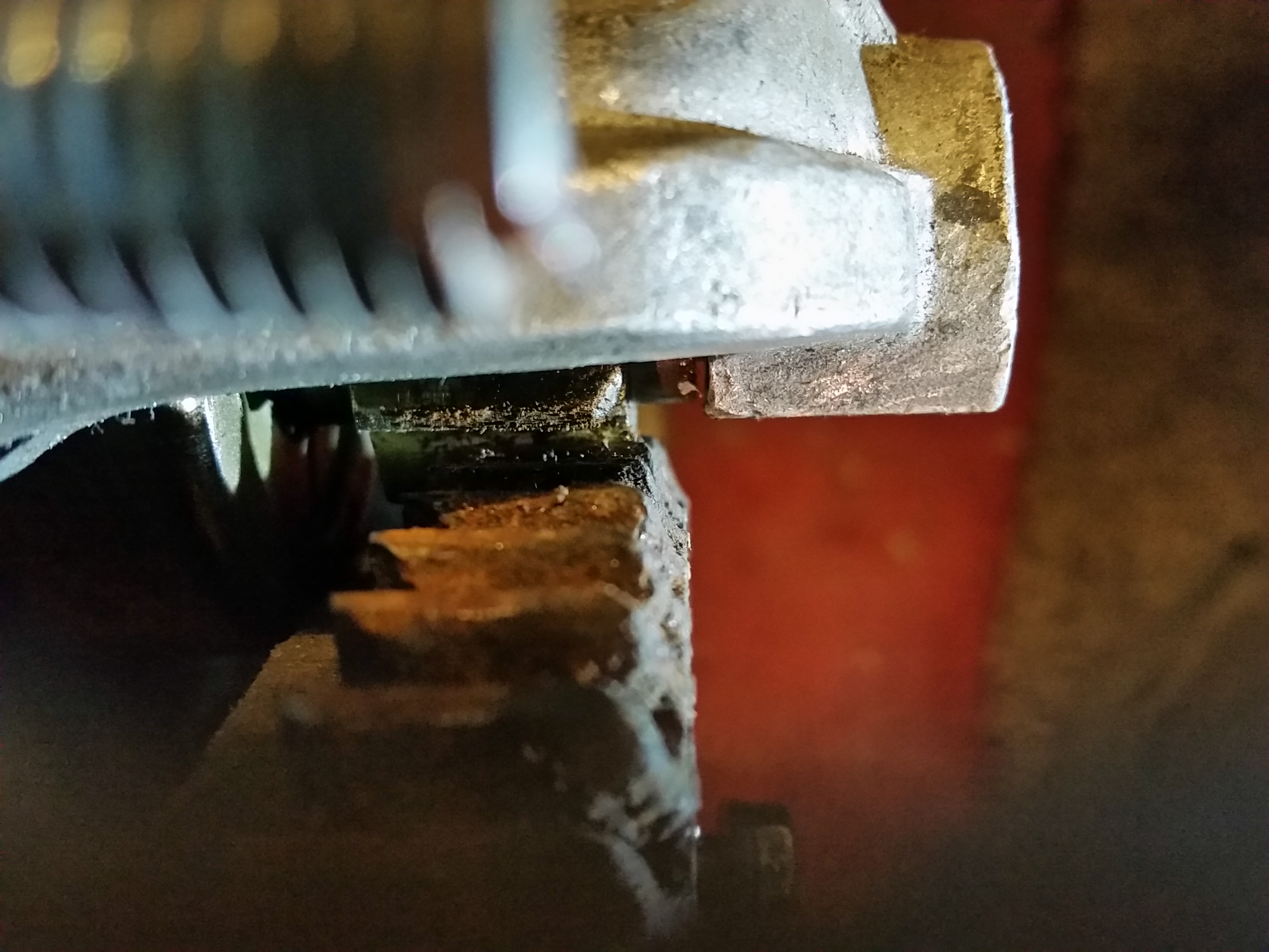
Then on to the the flange for the starter. It needs to be a snug fit, so another
high tech special tool was implemented for marking out the hole.
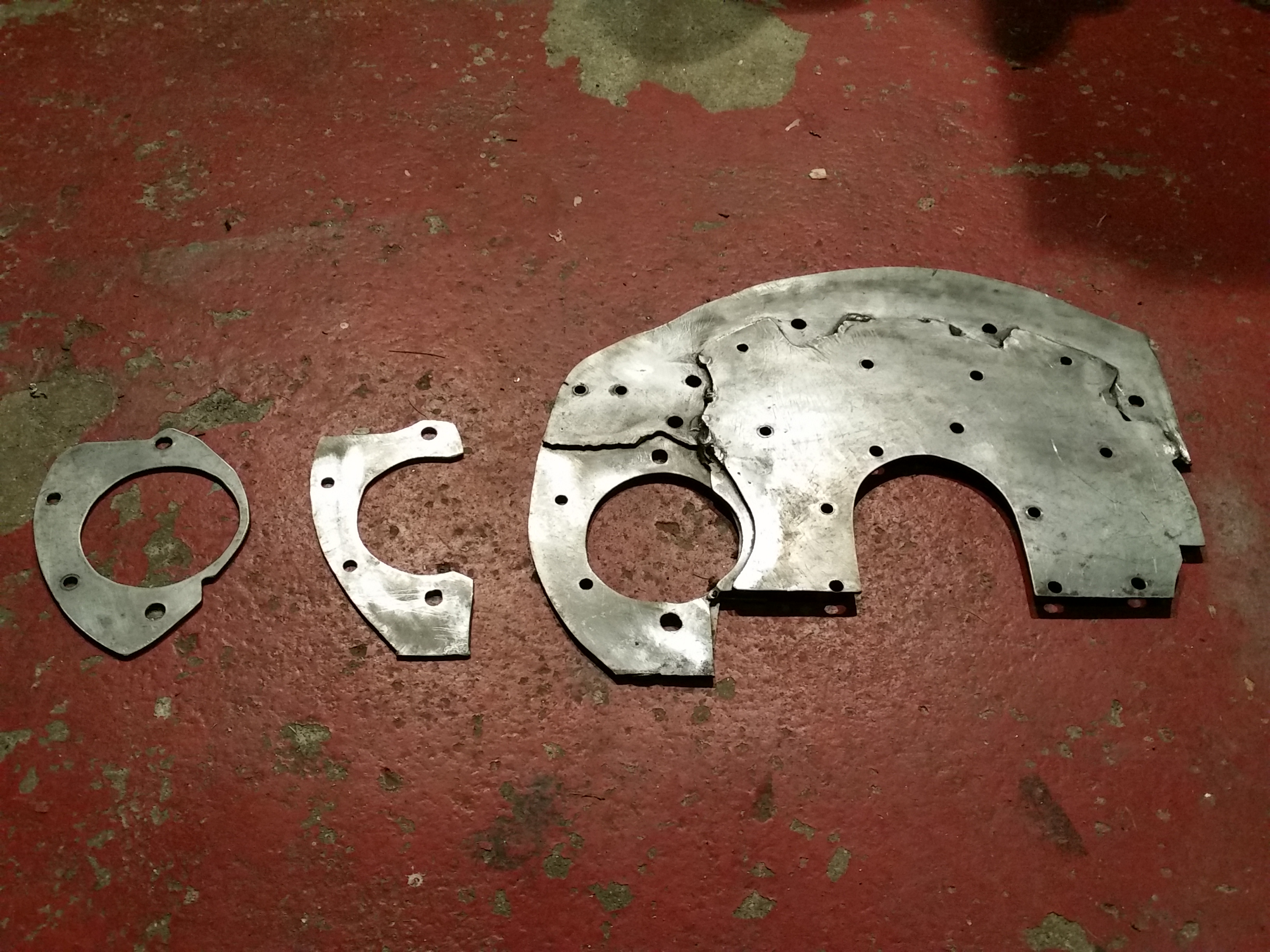
Starter flange, spacer and backplate